Pneumatic motorized multi-pump system

Inactive Publication Date: 2010-12-30
PATTON ENTERPRISES
View PDF11 Cites 0 Cited by
  • Summary
  • Abstract
  • Description
  • Claims
  • Application Information

AI Technical Summary

Benefits of technology

[0023]Embodiments of the pneumatic motorized multi-pump systemic methodology of the present invention invoke simple, inexpensive sealing technology for routinely sustaining contemplated differential pressure across the drive piston seal. As will be hereinafter elucidated, differential pressure manifest across the drive piston seal would preferably be equal to the pressure differential between the low pressure end of the drive cylinder and the high pressure end thereof. Unlike particular developments in the art, embodiments of the present invention are devoid of complicated, maintenance-prone piston shuttle valves and the like.
[0026]Furthermore, since embodiments of the instant pneumatic motorized multi-pump apparatus are not interconnected with external pumps, such embodiments do not need to be coordinated with the stroke lengths of external pumps; on the contrary, such embodiments have been independently designed and configured with relatively long stroke length and with relatively large diameter plungers. The consequent plurality of plungers and corresponding plurality of plunger-cylinders are disposed on opposite sides of the drive piston so that discharge pumping action would be manifest for all pumped fluids in both directions of the reciprocating pumping cycle. It will become evident to practitioners in the art that this phenomenon results in a high pumped volume per stroke-length, so that the pumping application requirements may be accomplished at relatively slower speeds, i.e., at relatively low strokes per minute, which has been found to significantly extend the longevity of seals and pneumatic controls.
[0027]Of course, this beneficial attribute is especially important for glycol pump applications which typically require 5 to 10 GPM (gallons per minute) as compared to chemical pump applications which typically require 5 to 50 GPD (gallons per day). It will be appreciated by practitioners in the art that existing pump technology under similar circumstances and conditions devolve to stand-alone drive units that are interconnected with external pumps, with one pump located on each end of the drive unit, and with each external pump therefore receiving discharge pumping action on only half of the reciprocating pumping cycle. In conjunction with the short stroke-lengths of these units, this means that such units must be operated at relatively high strokes per minute speeds, resulting in higher wear rates for seals, packing, controls and other pumping system components.
[0029]It will be appreciated that the accumulation of prior art attributes accounts for added seal friction-induced power losses and renders the seals more susceptible to wear and deterioration. For pumping applications contemplated hereunder, there is limited well gas differential pressure available for operating the implemented pumping system. Minimizing seal friction-induced power losses tends to assure that low-maintenance, uninterrupted pump performance is realized. Accordingly, embodiments of the present invention efficiently transfer power from the energy source—well gas differential pressure between pumping apparatus inlet and pumping apparatus outlet—to the fluid(s) being pumped.

Problems solved by technology

Since this low-pressure gas cannot be returned to the high-pressure gas flow line, this low-pressure gas is exhausted to the atmosphere, thereby causing pollution and simultaneously wasting valuable gas.
However, as is well known in the art, there are inherent problems associated with using a ventless gas drive apparatus connected to external reciprocating pumps at remote, infrequently-attended natural gas well sites where the equipment must operate continuously, i.e., operate 24 hours per day, every day of the year.
It is also not unusual for natural gas wells to be located in adverse and even in harsh environments.
Unfortunately, commercially-available reciprocating pumps require frequent maintenance to enable ongoing operation.
In particular, such reciprocating pumps require periodic packing adjustment and concomitant lubrication-service.
Reciprocating pumps are notoriously prone to both packing and seal leakage, and, therefore, in order to accommodate continual operation in the field, reciprocating pumps must be augmented with elaborate leakage-drain systems.
But, ironically, while being implemented to promote continual operation of gas-driven reciprocating pumps, such elaborate leakage-drain systems, per se, require constant monitoring and maintenance.
Another limiting issue of ventless drive apparatus known to practitioners in the art is that the drive unit has a predefined stroke-length.
This tends to limit the pumping range available from a driven external reciprocating pump which normally has a variable stroke-length.
It should be evident that this situation complicates coordination of simultaneous operation of the two external pumps.
For instance, for the instant exemplary field application, it is difficult for an operator to optimally set the pumping requirements simultaneously for both external pumps.
This daunting challenge may compel an operator to run the external pumps at suboptimal settings.
It should be apparent that these maintenance and design issues tend to severely militate against practical application of such pumping systems at remote well sites that are only rarely scheduled to be serviced by operating personnel and that are dispersed over a wide geographical area, often in adverse and even harsh environments.
As is common knowledge in the art, there are often hundreds of wells in a gas field, with frequent maintenance being neither practicable nor affordable.
Moreover, in view of contemporary environmental regulations, pumping operations which are characterized by chronic seal and packing leakage problems—resulting in emissions of contaminants, including well gas, glycol, methanol, corrosion inhibitor, etc., into the environment is unacceptable and may be unlawful.
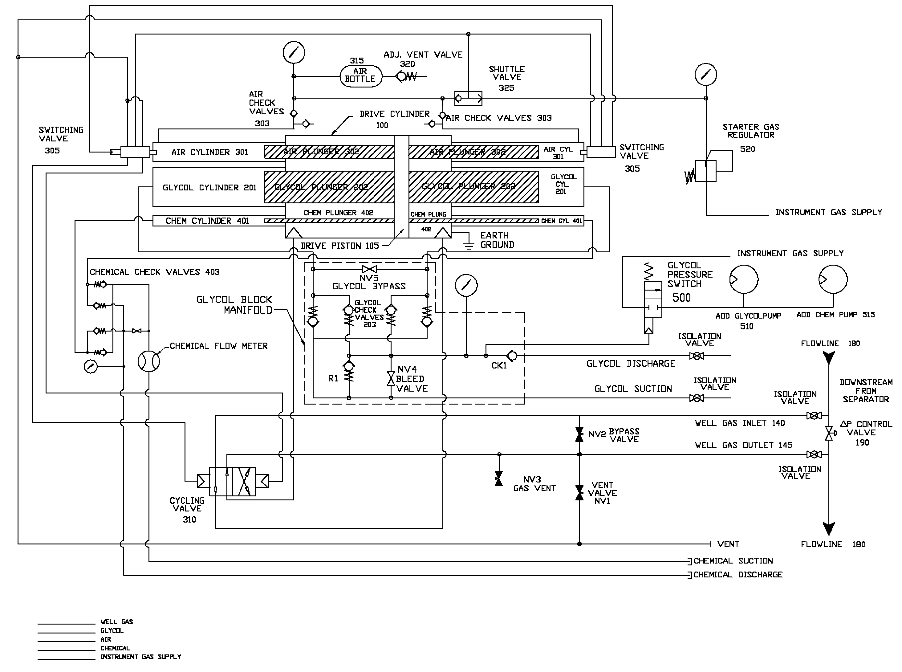
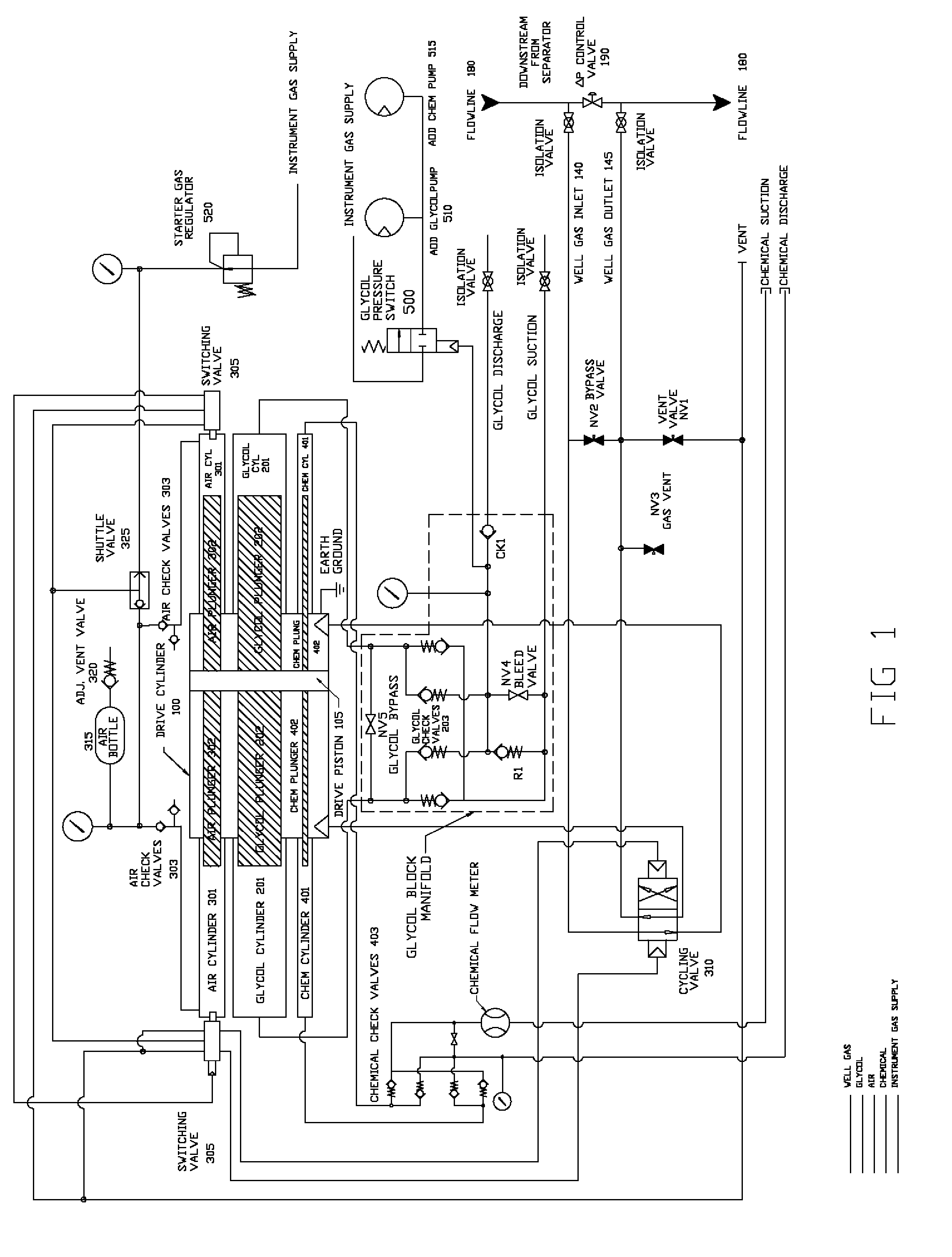
One of the significant drawbacks and disadvantages of the prior art exemplified by Paval and Grimes is that such embodiments of ventless gas drive apparatus are stand-alone drive units interconnected with external reciprocating pumps via a piston rod.
Accordingly, embodiments of this art are susceptible to the hereinbefore elucidated operational problems and limitations.
Another significant drawback and disadvantage of the Paval and Grimes ventless gas drive units is that both prior art pump systems invoke spaced-apart circumferential piston seals to prevent flow of gas between the two ends of the drive cylinder.
The high differential pressure acting across the seals causes high frictional forces which, in turn, reduces available power output from the drive and induces faster seal wear than if the pressure differential were significantly lower.
However, the differential shuttle valve system contained within the piston of the Paval drive introduces considerable complexity to the piston assembly which ramifies not only as higher cost, but also as more recurring maintenance.
The small apertures and small passageways and moving parts of the prior art shuttle valve system are highly prone to becoming plugged and stuck under these conditions.
Since the Paval shuttle valve system can be cleaned out and repaired only by taking the complete drive out of service, the Paval shuttle valve methodology therefore inflicts yet another level of maintenance concerns that militates against uninterrupted pumping operation at gas wells in the field.
Yet another significant drawback and disadvantage of the Paval and Grimes ventless gas drives is the use of high pressure raw well gas to actuate the end-of-stroke switching and cycling control valves.
Often the pumping system will be located downstream from a gas-liquid separator and / or filter but, as is well known in the industry, some liquids and fine solids still often bypass these devices and therefore flow through the pumping system.
The small apertures and small passageways and moving parts associated with the end-of-stroke switching and cycling control valves are highly prone to plugging up and sticking under these conditions.
This prior art method of controlling the end-of-stroke switching and cycling of the drive unit therefore introduces still another maintenance issue to an already saturated, onerous maintenance scenario as hereinbefore described.
Such prior art pumping technology suffers from inherent operational and maintenance problems as hereinbefore described.

Method used


Image

  • Pneumatic motorized multi-pump system
  • Pneumatic motorized multi-pump system
  • Pneumatic motorized multi-pump system

Examples


Embodiment Construction

[0036]As will become clear to those skilled in the art, preferred embodiments of the pneumatic motorized multi-pump system of the present invention are comprised of a drive cylinder having a drive piston and a plurality of interconnected plungers and corresponding plurality of plunger-cylinders. More particularly, each of a pair of plungers is interconnected on an opposite side of the drive piston. Each plunger, in turn, passes through a sealed opening in its respective end of the drive cylinder and then passes into a corresponding plunger-cylinder interconnected at its respective end of the drive cylinder. As the drive piston alternately moves back and forth under the influence of differential pressure as herein described, the drive piston pushes and pulls the plurality of plungers in and out of their corresponding plurality of plunger-cylinders, respectively, thereby generating the pumping cycles of the present invention.

[0037]As herein described, one pumping cycle consists of a d...


PUM


Abstract

Motorized single-machine multi-pump apparatus and closed-loop methodology interconnected with a gas pipeline at a natural gas production well, using pressurized gas flow and differential pressure to drive a pumping system regulated by pneumatic controls using self-generated clean, low-pressure instrument air. The apparatus is connected to the gas flow line and the outlet is connected back into the gas flow line at lower pressure, creating a differential pressure corresponding to the source of motive power for actuating a piston which is directly connected to a plurality of plungers. This plurality of plungers is alternately pushed into and pulled out of corresponding plunger-cylinders for creating an integral drive and pump system prerequisite for gas well site pumping operations. Instead of venting to the atmosphere, well gas is returned to the flow line whereupon only clean air from the self-generated instrument air circuit is vented into the atmosphere.

Description

RELATED APPLICATIONS[0001]This application claims priority based upon U.S. application Ser. No. 11 / 449,293 filed Jun. 8, 2006, which claimed priority based upon Provisional U.S. Application Ser. No. 60 / 015,744 filed Jun. 8, 2005.FIELD OF THE INVENTION[0002]The present invention relates to pumping systems, and more particularly, relates to an apparatus and methodology that incorporates multiple process pumps and a ventless gas drive mechanism into one machine that is controlled by pneumatic valves and switches using a self-generated supply of clean low pressure air.BACKGROUND OF THE INVENTION[0003]At natural gas production well sites and at other natural gas production facilities there is a requirement for process pumps to perform various applications. One application is to inject chemical into the well bore. A common example of this application is the injection of methanol into a well bore to inhibit the formation of hydrates. Another common example is the injection of a corrosion i...

Claims


Application Information

Patent Timeline
IPC IPC(8): F04B47/08
CPCF04B47/08F04B9/12
Inventor THRASHER, WILLIAM B.PATTON, MARK V.
Owner PATTON ENTERPRISES
Why Eureka
Try Eureka