Thermally conductive cementitious grout for geothermal heat pump systems

a technology of cementitious grout and geothermal heat pump, which is applied in the direction of sealing/packing, borehole/well accessories, insulation, etc., can solve the problems of affecting the drilling cost, the cost of the pipe and the size of the pump, and the inability of the ghp system to be a practical alternative energy sour

Inactive Publication Date: 2001-06-26
THE UNITED STATES AS REPRESENTED BY THE DEPARTMENT OF ENERGY
View PDF12 Cites 110 Cited by
  • Summary
  • Abstract
  • Description
  • Claims
  • Application Information

AI Technical Summary

Problems solved by technology

An important factors in determining the feasibility of a GHP system is the depth of wellbore, which affects the drilling costs, the cost of the pipe and the size of the pump.
If the wellbore has to be drilled to too great a depth, a GHP system may not be a practical alternative energy source.
The thermal conductivity of the grout has a significant impact on the required depth of the wellbore and, hence, the installation costs.
A grout that does not efficiently conduct heat can act as an insulator and reduce the efficiency of the GRP system.
Although bentonite has good sealant properties, it has a relatively low thermal conductivity.
Neat cement grouts have also been used with some degree of success, but high water to cementitious materials (w/c) ratios of

Method used


Image

  • Thermally conductive cementitious grout for geothermal heat pump systems
  • Thermally conductive cementitious grout for geothermal heat pump systems
  • Thermally conductive cementitious grout for geothermal heat pump systems

Examples


example 2

The water coefficient of permeability (hydraulic conductivity) of the various cement-sand grout formulations of the present invention under saturated conditions was measured in a flexible wall triaxial cell permeameter on cylindrical specimens 102 mm in diameter and 70 mm long. The permeant was de-aired tap water at room temperature. The applied pressure gradient was 207 kPa (30 psi) over the length of the specimen. The confining pressure applied to seal a latex membrane to the side surface of the grout specimen was 414 kPa (60 psi). The experimental set-up followed that given in ASTM D 5084-90. The results from these permeability tests for cement-sand grouts of the present invention are listed in Table 7.

example 3

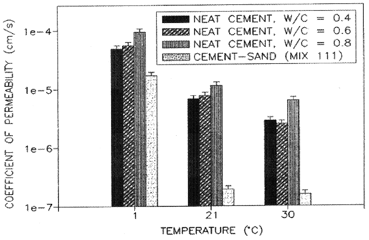
In order to compare the hydraulic sealing capability of the cement-sand grouts of the present invention with cementitious grouts used in the prior art, tests were conducted with neat cement grouts. The neat cement grouts were tested at different water to cement ratios and different temperatures to determine how changes to the water to cement ratio and temperature affects the permeability of the neat cement grouts. The results are shown in Table 8.

The results of the permeability tests for the cement-sand grouts of the present invention and the neat cement grouts, when bonded to HDPE pipes, are shown in graphical form in FIG. 1. The graph shows that over a temperature range of from 1.degree. C. to 30.degree. C., the cement-sand grouts of the present invention are less permeable and have superior sealing characteristics than neat cement grouts. The difference in permeabilities of the grout / pipe specimens increased as the temperature increased and the greatest difference in permeability...

example 4

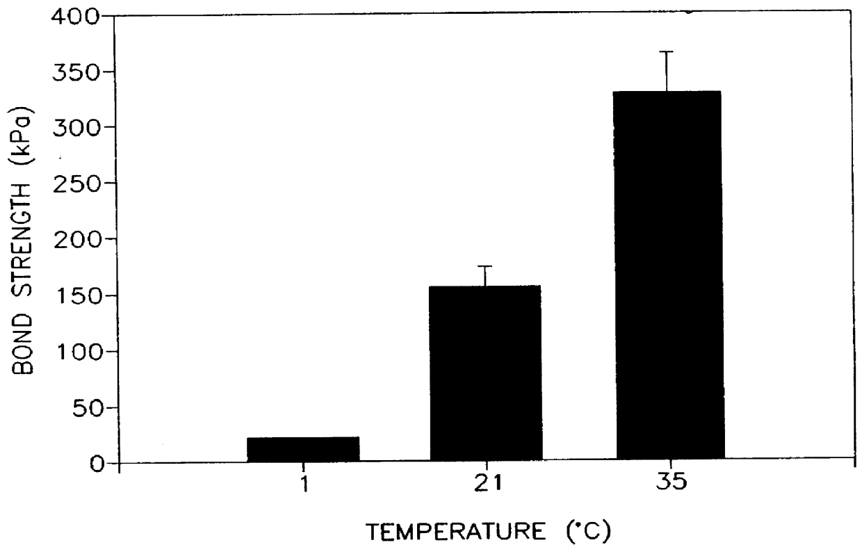
Mix No. 111 is one of the preferred cement-sand grouts of the present invention and its permeability, when bonded to HDPE pipes, was measured over a temperature range of from 1.degree. C. to 350C and compared to a commercially available grout (Conbextra S) measured at 21.degree. C. The results from these tests are listed in Table 9. These tests show that Mix No. 111 had a substantially lower system permeability than Conbextra S at 21.degree. C.


PUM

PropertyMeasurementUnit
Fractionaaaaaaaaaa
Fractionaaaaaaaaaa
Fractionaaaaaaaaaa

Abstract

A thermally conductive cement-sand grout for use with a geothermal heat pump system. The cement sand grout contains cement, silica sand, a superplasticizer, water and optionally bentonite. The present invention also includes a method of filling boreholes used for geothermal heat pump systems with the thermally conductive cement-sand grout. The cement-sand grout has improved thermal conductivity over neat cement and bentonite grouts, which allows shallower bore holes to be used to provide an equivalent heat transfer capacity. In addition, the cement-sand grouts of the present invention also provide improved bond strengths and decreased permeabilities. The cement-sand grouts can also contain blast furnace slag, fly ash, a thermoplastic air entraining agent, latex, a shrinkage reducing admixture, calcium oxide and combinations thereof.

Description

BACKGROUND OF INVENTIONThe present invention relates to grout for use with geothermal heat pump systems. In particular, the present invention relates to cement-sand grouts having improved thermal conductivity, as well as increased bond strength and decreased permeability.Geothermal heat pump (GHP) systems for recovering energy from the ground are well known. The temperature of the Earth increases with increasing depth, to 400-1800.degree. F. at the base of the Earth's crust and to an estimated temperature of 6300-8100.degree. F. at the center of the Earth. Geothermal energy is present everywhere beneath the Earth's surface, but in order to be used as a source of energy, it must be accessible to drilling and, therefore, must be relatively close to the surface. Since a major cost in geothermal development is drilling and since the cost of drilling increases with increasing depth, shallow concentration of geothermal energy are preferred. The most conspicuous use of geothermal energy is...

Claims


Application Information

Patent Timeline
IPC IPC(8): C04B28/00C04B28/02C09K8/42C09K8/46
CPCC04B28/02C09K8/46C04B14/06C04B14/104C04B18/141C04B22/064C04B24/226C04B24/26C04B18/08C04B2111/34C04B2111/70C04B2103/304C04B2111/00706Y02W30/91
Inventor ALLAN, MARITA
Owner THE UNITED STATES AS REPRESENTED BY THE DEPARTMENT OF ENERGY
Why Eureka
Try Eureka