Solenoid valve for a slip-regulated hydraulic brake system of a vehicle

a technology of hydraulic brake system and solenoid valve, which is applied in the direction of valve housing, braking system, operating means/releasing devices, etc., can solve the problem of relatively high cost of manufacture and assembly of the known solenoid valv

Inactive Publication Date: 2001-07-03
ROBERT BOSCH GMBH
View PDF8 Cites 66 Cited by
  • Summary
  • Abstract
  • Description
  • Claims
  • Application Information

AI Technical Summary

Problems solved by technology

The valve support is sealed in the hydraulic block by means of two O-rings, which makes manufacture and assembly of the known solenoid valve relatively costly since O-ring grooves have to be let into the valve support and the O-rings must be inserted into the O-ring grooves before the insertion of the solenoid valve into the hydraulic block.

Method used


Image

  • Solenoid valve for a slip-regulated hydraulic brake system of a vehicle
  • Solenoid valve for a slip-regulated hydraulic brake system of a vehicle
  • Solenoid valve for a slip-regulated hydraulic brake system of a vehicle

Examples


Embodiment Construction

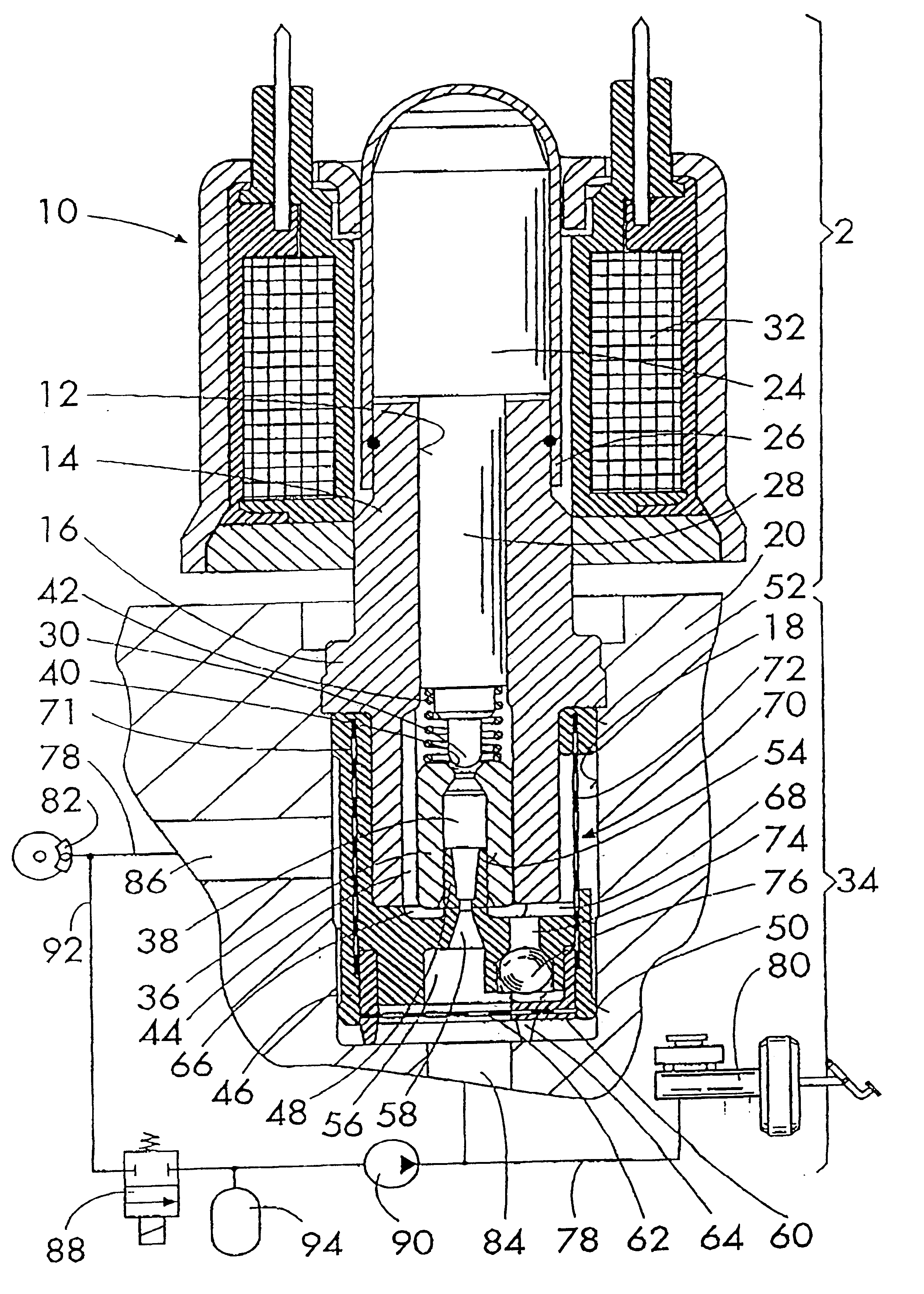
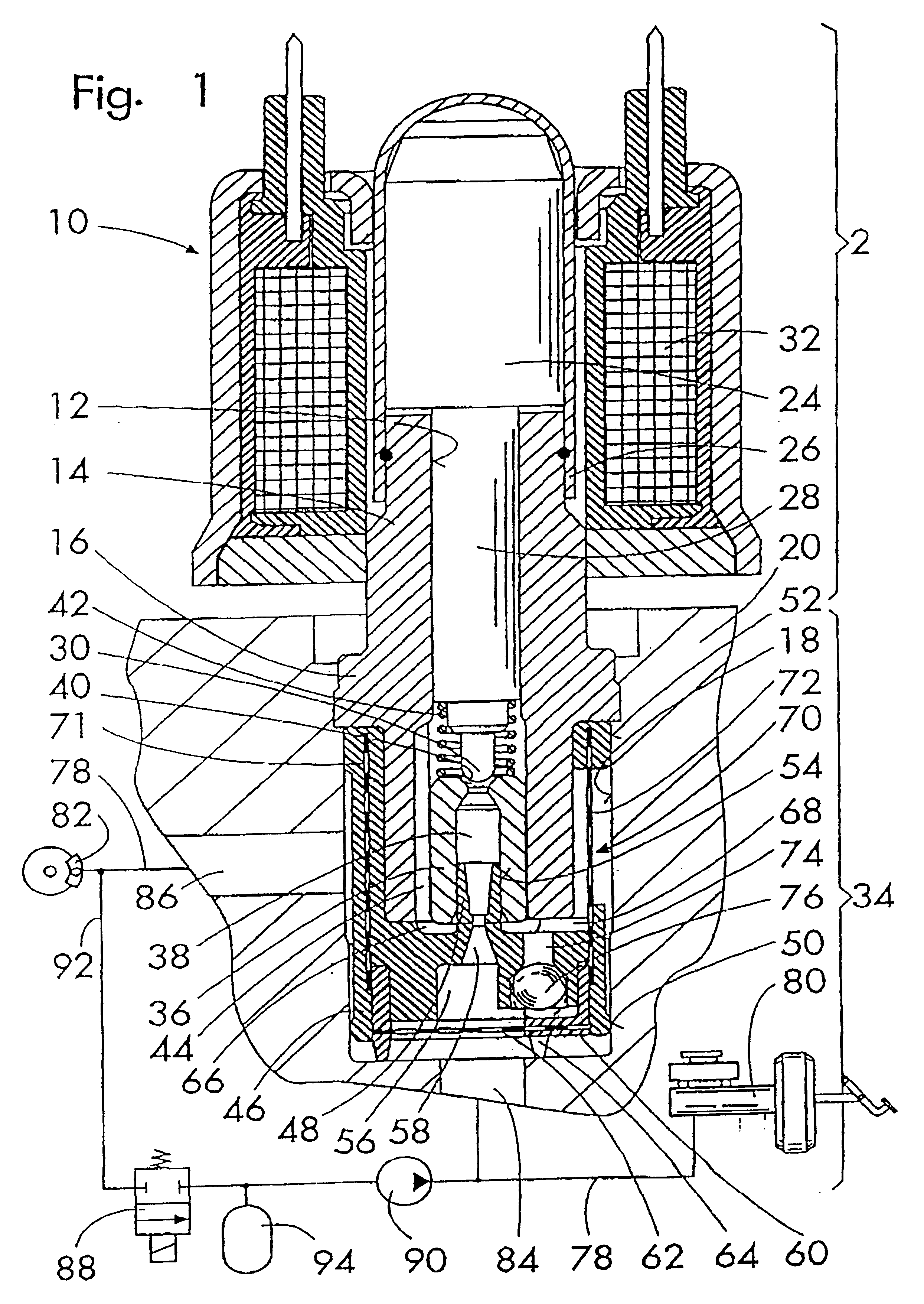
The rod-shaped solenoid valve 10 according to the invention depicted in FIG. 1 has a rotationally symmetrical valve support 14, which is provided with an axial through bore 12 and has a fastening flange 16 that is an integral part of the valve support and is disposed approximately in the middle of its length. The valve support 14 is inserted into a receiving bore 18 in a hydraulic block 20 and is secured by caulking on its fastening flange 16. A hydraulic part 34 of the solenoid valve 10 is disposed in the hydraulic block 20, a magnetic part 22 protrudes from the hydraulic block 20. The valve support 14 is an extruded part that is produced in one work cycle and does not have undercuts.

On an end face of the valve support 14 remote from the hydraulic block 20, the magnetic part 22 has an axially movable armature 24 contained in a valve dome 26, which is welded to the valve support 14 in a fluid tight manner. A valve tappet 28 extends from the armature 24 into the through bore 12 of th...


PUM


Abstract

A rod-shaped solenoid valve that is provided for insertion into a receiving bore of a hydraulic block of an antilock hydraulic brake system of a vehicle, wherein a fluid influx takes place through an axial bore of a valve seat part that is inserted into a valve support. For simple sealing, a plastic end piece is placed onto the end of the valve support that prodrudes into the receiving bore and seals the valve support in relation to the receiving bore and also seals the valve seat part.

Description

PRIOR ARTThe invention is based on a solenoid valve, which is provided for insertion into a receiving bore in a hydraulic block of a slip-regulated hydraulic brake system of a vehicle. It is in particular provided as an inlet valve preceding a wheel brake cylinder or as a reversing valve connected between the master cylinder and the rest of the vehicle brake system.A valve of this kind has been disclosed by DE 44 12 648. This valve is embodied as rod-shaped and has a rotationally symmetrical valve support with an axial through bore. For the purpose of a hydraulic connection, the valve support is provided for insertion into a receiving bore of a hydraulic block so that an inlet on an end face of the valve support and an outlet on the circumference of the valve support communicate with fluid conduits of the hydraulic block, which feed into the receiving bore in a bottom face or on the circumference.The valve support protrudes with a part of its length out of the hydraulic block. A val...

Claims


Application Information

Patent Timeline
Patent Type & Authority Patents(United States)
IPC IPC(8): B60T8/36
CPCB60T8/363Y10T137/8122Y10T137/86348B60T8/36
Inventor MEGERLE, FRIEDRICHFRITSCH, SIEGFRIEDKIRSCHNER, MARTIN
Owner ROBERT BOSCH GMBH
Why Eureka
Try Eureka