Substrate temperature control method and device

Inactive Publication Date: 2001-07-03
PANASONIC CORP
View PDF7 Cites 37 Cited by
  • Summary
  • Abstract
  • Description
  • Claims
  • Application Information

AI Technical Summary

Problems solved by technology

However, there are the following problems with the above prior art construction.
A further problem was that the evacuation time after completion of plasma processing was also long, owing to the large evacuation resistance of automatic pressure control valve 115 when the pressure was lowered by fully opening automatic pressure control valve 115.
The conventional plasma processing apparatus therefore suffered from the problems of generation of dust at the under-surface of the substra

Method used


Image

  • Substrate temperature control method and device
  • Substrate temperature control method and device
  • Substrate temperature control method and device

Examples


Example

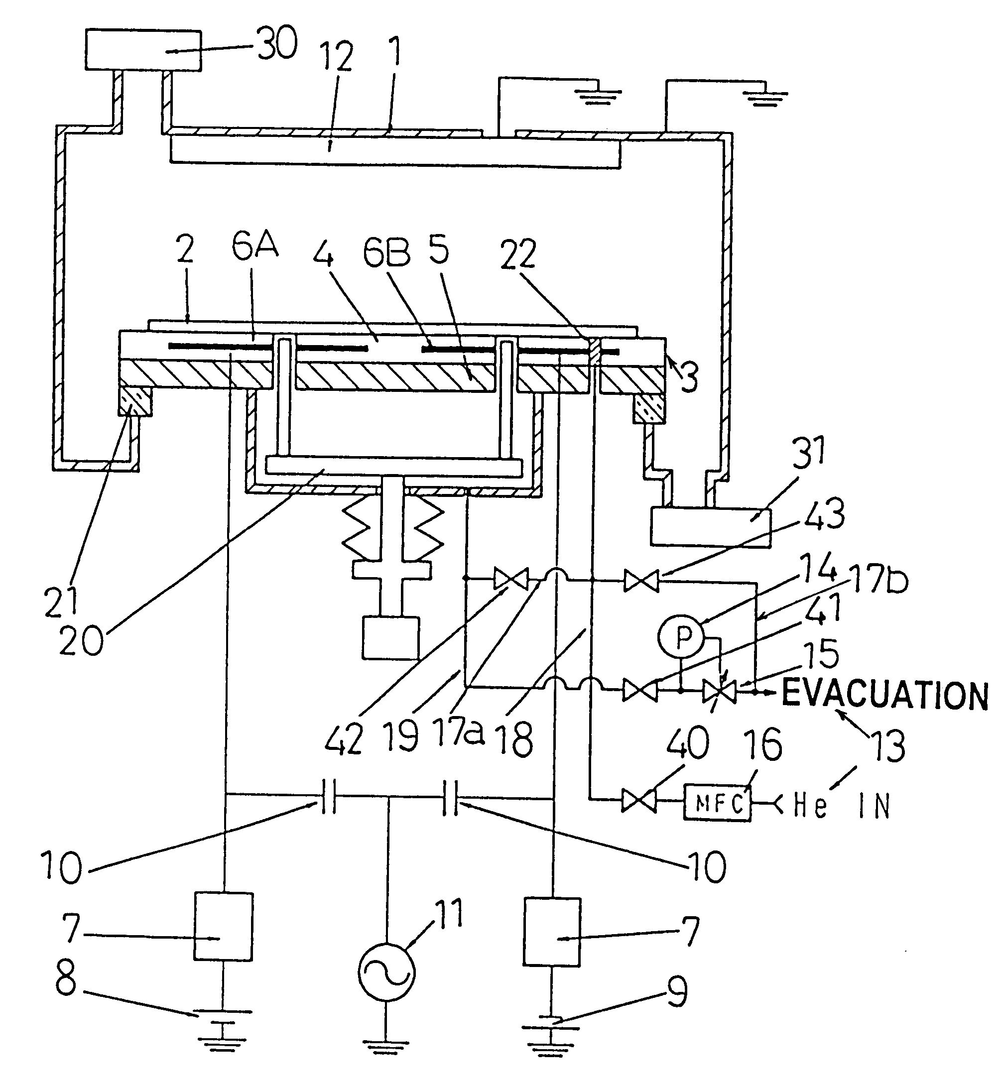
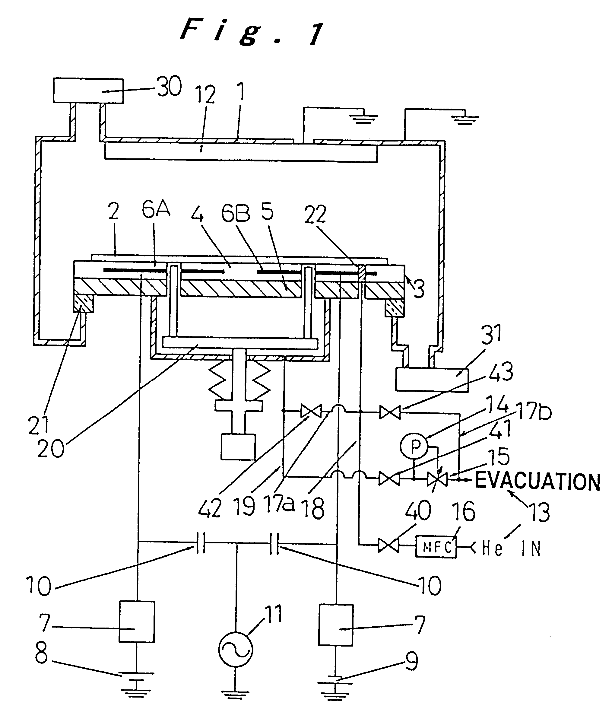
An embodiment wherein a substrate temperature control device according to the present invention is applied to a reactive ion etching-type dry etching apparatus is described below with reference to FIG. 1.

In FIG. 1, 1 is a vacuum chamber having means for reactive gas supply 30 and means for vacuum evacuation 31, 2 is a substrate such as a silicon wafer constituting the item under treatment, and 3 is an electrostatic attraction-type substrate holder, comprising an alumina dielectric part 4 of thickness 5 mm and an aluminum base part 5 provided with a cooling water passage (not shown). A pair of electrostatic attraction internal electrodes 6A, 6B made of tungsten are embedded 500 .mu.m within the outer surface of alumina dielectric part 4. Substrate push-up mechanism 20 for substrate feed purposes is provided in the interior of substrate holder 3. 21 is a spacer made of ceramics, which electrically insulates vacuum chamber 1 and substrate holder 3. A hole for supplying heat-conductive ...


PUM

PropertyMeasurementUnit
Porosityaaaaaaaaaa
Temperatureaaaaaaaaaa
Pressureaaaaaaaaaa

Abstract

In processing the surface of a substrate 2 that is held with its under-surface in contact with a substrate holder 3 in a vacuum chamber 1, the temperature of substrate 2 is controlled by supplying a heat-conductive gas between the substrate 2 and substrate holder 3. Supply and evacuation of the heat-conductive gas are effected rapidly at high flow rate from both supply line 18 and evacuation line 19 using bypass lines 17a, 17b, while pressure regulation is effected with a low flow rate.

Description

1. Technical Field of the InventionThe present invention relates to a substrate temperature control method and device in a thin-film forming step in the manufacture of semiconductor elements, liquid crystal display panels or solar cells etc., or plasma processing apparatuses used in micro-processing steps.2. Description of Related ArtIn recent years, in plasma processing apparatuses, in order to achieve higher device functionality and lower processing costs, great efforts are being made to achieve higher precision, higher speeds, increase of area, and lower damage rates. In this connection, it is desired in particular to achieve uniform and precise control of the substrate temperature over its surface in order to obtain uniformity of film quality within the substrate during deposition and to ensure dimensional accuracy in the dry etching which is used in micro-processing. In order to achieve this, mechanical clamps or electrostatic attracting electrodes are employed as means for con...

Claims


Application Information

Patent Timeline
IPC IPC(8): C23C16/46C23C16/458H01J37/32H01L21/00H01L21/302H01L21/3065H01L21/683
CPCC23C16/4586C23C16/46H01L21/67103H01J37/32431H01J2237/2001
Inventor MATSUDA, IZURUHARAGUCHI, HIDEO
Owner PANASONIC CORP
Why Eureka
Try Eureka