

Laser thermal media with improved abrasion resistance
- Summary
- Abstract
- Description
- Claims
- Application Information
AI Technical Summary
Benefits of technology
Problems solved by technology
Method used
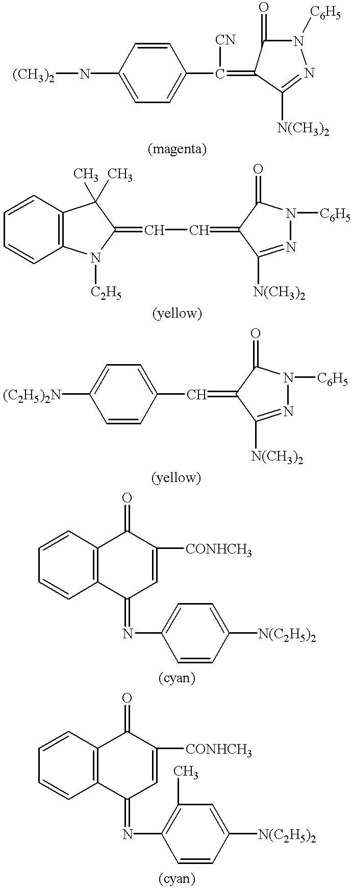
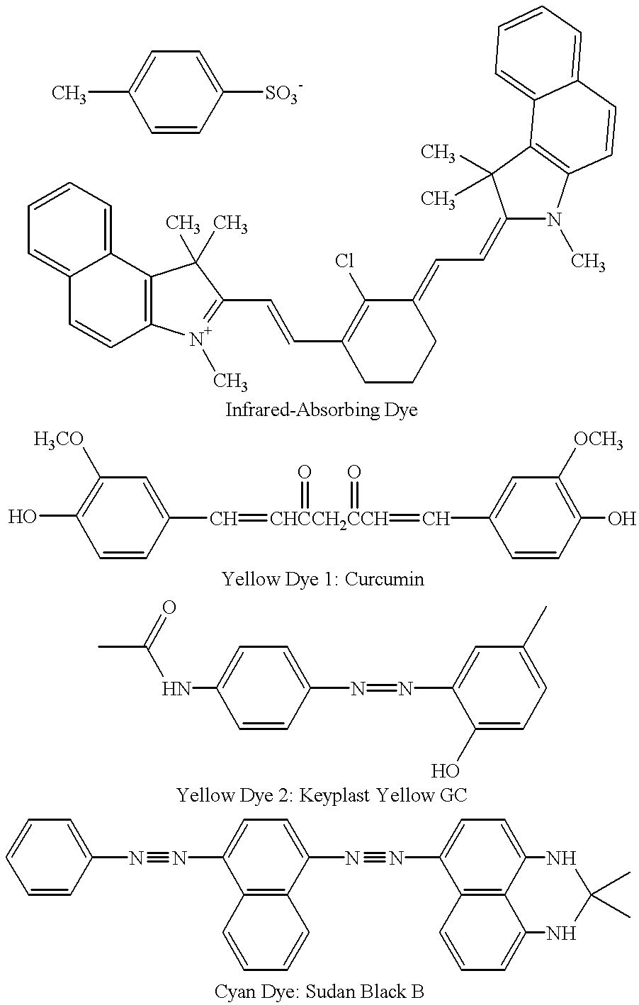
Image

Examples
example 1
Onto a 100 .mu.m poly(ethylene terephthalate) support was coated a compliant layer of Polymer B. Onto this layer was coated the following layers in this order:
Subbing (barrier) layer:
Top Particle Layer:
A sample of coated media was tested using a Taber test which consists of placing a small rotating abrasive disk on the surface of the film. A 125 g of weight was applied and 50 cycles were conducted. The Taber instrument spins the weighted abrasive disk and rotates it in a circle around the film creating a ring of abraded film. The UV density of the abraded regions was measured on an X-Rite (Model 361 T) UV densitometer (X-Rite Inc.). Four measurements at different locations were averaged in both the abraded and the Dmax (unabraded) regions. The results are shown in Table 1.
The above results show that use of a compliant layer in accordance with the invention provided improved abrasion resistance as shown by the reduced density loss.
Printing The above element was ablation ...
example 2
In this experiment, different laydowns of polymer A were hot melt extruded onto a 100 .mu.m poly(ethylene terephthalate) support and the barrier layer, imaging layer, and top particle layer of Example 1 were applied. The abrasion test was conducted as in Example 1. The following results were obtained:
The above results show that use of a compliant layer in accordance with the invention provided improved abrasion resistance as shown by the reduced density loss.
example 3
This example is the same as Example 1 except for using a water coatable compliant layer, Polymer C, instead of Polymer B. The coating levels are given in Table 3. The following results were obtained:
The above results show that use of a compliant layer in accordance with the invention provided improved abrasion resistance as shown by the reduced density loss.
PUM
| Property | Measurement | Unit |
|---|---|---|
| Nanoscale particle size | aaaaa | aaaaa |
| Fraction | aaaaa | aaaaa |
| Fraction | aaaaa | aaaaa |
Abstract
Description
Claims
Application Information