Paddle wheel boat

a technology of paddle wheel boats and propellers, which is applied in the direction of steering components, floating buildings, water-acting propulsive elements, etc., can solve the problems of high objectionable noise of air boats, inability to traverse under low hanging limbs, and existing paddle wheel boat designs experiencing steering problems, etc., and achieves high maneuverability

Inactive Publication Date: 2001-07-24
PRICE HAROLD L
View PDF14 Cites 20 Cited by
  • Summary
  • Abstract
  • Description
  • Claims
  • Application Information

AI Technical Summary

Benefits of technology

to provide a highly maneuverable paddle wheel boat. This is accomplished, in part, through the relatively light weight of the unit affording a shallow draft boat, but mainly accomplished by the large bow mounted rudder.

Problems solved by technology

However, due to the excessive height of the propeller cage, they cannot traverse under low hanging limbs.
Also, in most areas, the excessive noise of the air boat is highly objectionable.
Existing paddle wheel boat designs experience steering problems when attempting to traverse marshy areas of dense moss and saw-grass growth due to the fact that the steering is mounted at the stem of the boat and is designed to maneuver the stem of the boat to the side to align with the bow of the boat to effect change of direction.
Another problem common to present paddle wheel boat design is that the entire weight of the propulsion device is cantilevered behind the stem of the boat causing a severe imbalance of weight distribution toward the stem of the craft.
This limits the craft to very slow speeds of operation because, when powered up, the nose of the boat rears upward and the paddle wheel starts to dig in and becomes submerged past the point of effective operation in that an excessive downward thrust is transmitted to the stern of the craft by the upswing of the deeply submerged propelling paddles.

Method used


Image

  • Paddle wheel boat
  • Paddle wheel boat
  • Paddle wheel boat

Examples


Embodiment Construction

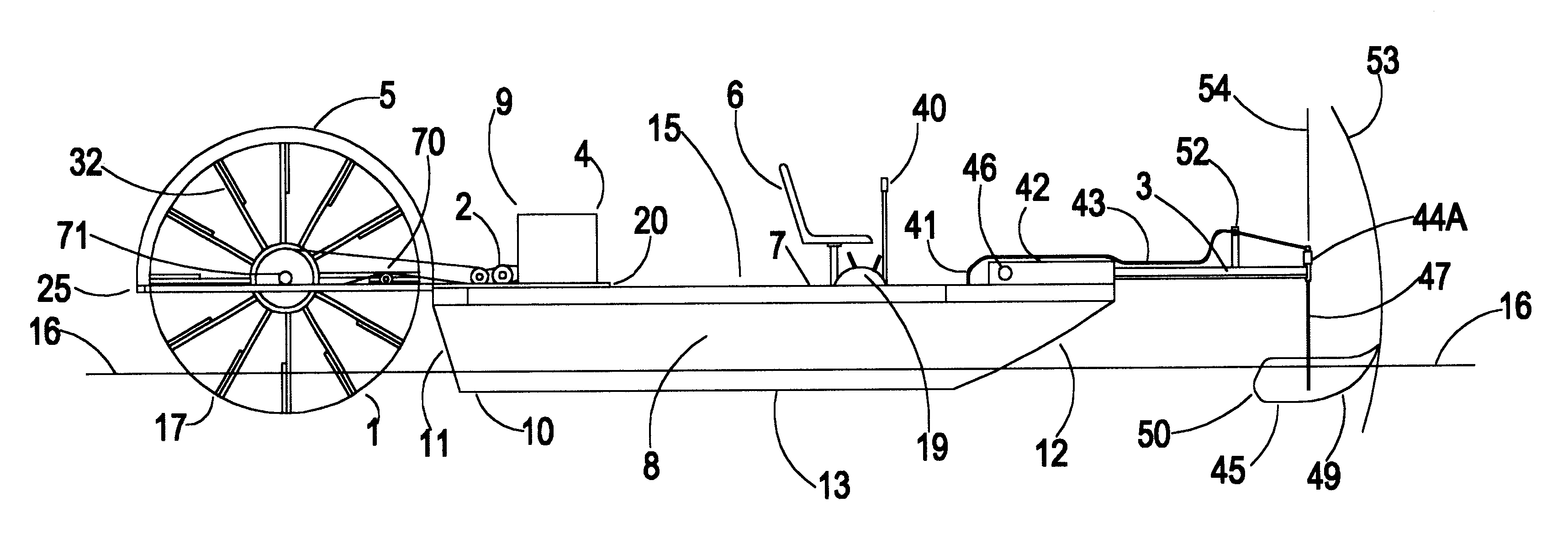
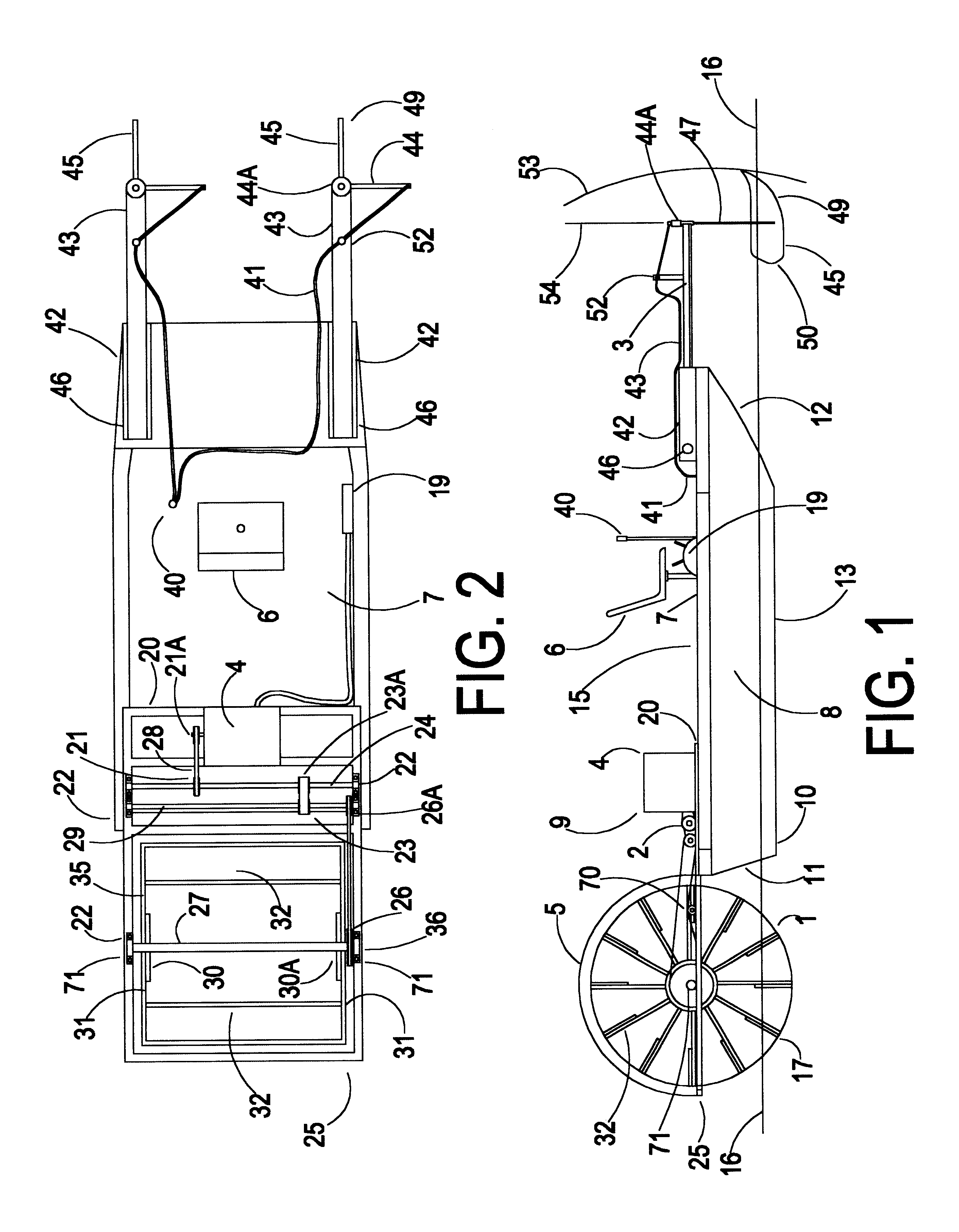
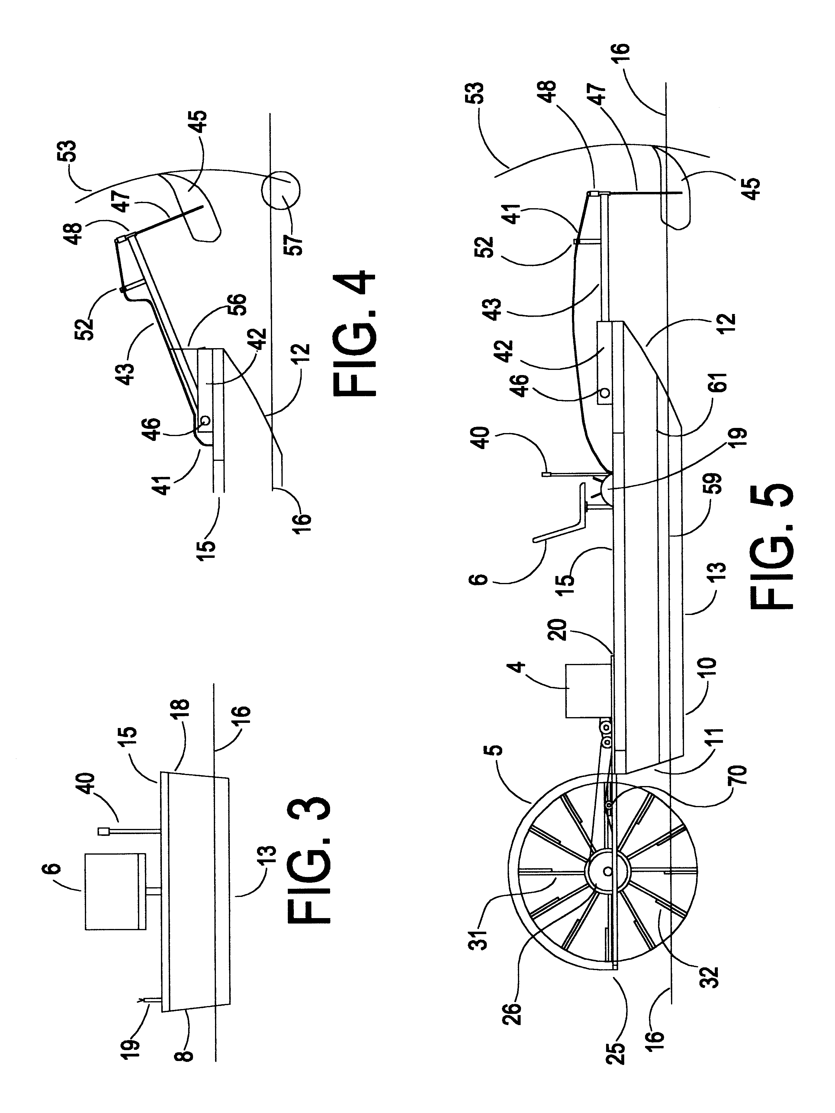
The vessel of this invention provides a highly maneuverable paddle wheel boat. This is accomplished, in part, through the relatively light weight of the unit affording a shallow draft boat, but mainly accomplished by the large bow mounted rudder. The bow mounted rudder, to effect a change of direction, utilizes the principle of moving the bow of the boat to one side in the desired direction to realign the bow with the stem in the desired direction of movement, thus allowing the stem to remain in the trail of the boat at all times and allowing the bow and bottom of the boat to make a trail through vegetation and shallow waterways. In a turning maneuver in dense growth, such as saw-grass, the rudder actually utilizes the standing vegetation in making the turn. The vegetation imparts a sideward thrust against the leading side of the rudder, in effect, pushing it in the desired direction. The rudder, being hinged to the boat at the inboard end of the rudder support member and the channe...


PUM


Abstract

The vessel of this invention has a relatively uniform weight distribution throughout the length of the vessel which maintains a level trim under all operation conditions thereby maximizing the efficiency of the design and operation. This is, in part, accomplished by locating the engine and major transmission drive components inboard of the boat rather than outboard astern, and by locating the operator and the rudder assembly at the bow of the boat. Unique features of the invention include the propulsion and steering systems consisting of a paddle wheel, a power supply, a clutch, a gear reduction system to transfer power to the paddle wheel, an optional splash guard mounted between the stern of the boat and the paddle wheel, a frame to attach the propulsion members to the boat and a rudder mounted to the bow of the boat. The paddle wheel can comprise blades secured to angled spokes at an angle skewed to the axis of rotation of the paddle wheel rather than extending radially from the axis of rotation of the center hubs to effect vertical lift. The steering apparatus comprises the rudder mounted at the bow of the boat and being formed and arranged to pivot freely about a horizontal axis in a vertical direction as well as pivot horizontally about a vertical axis.

Description

BACKGROUND AND PRIOR ARTThis invention relates to the propulsion and steering of paddle wheel boats, more particularly a propulsion and steering unit which may be fitted to an existing craft or to any specially designed craft, to which addition of said unit renders it capable of navigating any and all navigable waterways, as well as, waterways heretofore considered difficult or impossible to navigate, such waterways are shallow and contain logs, stumps, sandbars, mud-flats, vegetation in the water, growing out of the water and mud and hanging over the waterway or streams, and such waterways comprise swamps and marshes with dense aquatic growth such as moss, cattails and saw-grass, or heavy brush growth with low hanging limbs.No other single craft available today has the capacity to navigate or traverse, with ease and maneuverability, the wide range of terrain which can be traversed by the vessel of this invention. An air boat is capable of traversing shallow, dense aquatic growth ma...

Claims


Application Information

Patent Timeline
Patent Type & Authority Patents(United States)
IPC IPC(8): B63H25/38B63H5/02B63H25/06B63H5/00
CPCB63H5/02B63H25/38B63H2025/066B63H2025/063
Inventor PRICE, HAROLD L.
Owner PRICE HAROLD L
Why Eureka
Try Eureka