Apparatus and method for sputtering

a cylindrical magnetron and apparatus technology, applied in the direction of vacuum evaporation coating, electrolysis components, coatings, etc., can solve the problems of low material utilization (approximately 25%) before necessary replacement of the target, and inability to achieve the effect of reducing the material thickness by 2.5 times, and avoiding the loss of plasma confinemen

Inactive Publication Date: 2001-07-24
BVBA EMIEL VANDERSTRAETEN
View PDF4 Cites 33 Cited by
  • Summary
  • Abstract
  • Description
  • Claims
  • Application Information

AI Technical Summary

Problems solved by technology

In the case of the planar magnetron, the race track and target are in a static condition, therefore, the erosion groove along the race track is narrow, causing rapid depletion of the target material being sputtered within this localized area, and resulting in low material utilization (approximately 25%) before necessary replacement of the target.
However, experimentation has shown that simply increasing the material thickness by 2.5 times while using the single magnetic race track configuration is not a feasible approach, because this methodology produces two undesirable effects.
The first problem is the reduction of the magnetic field strength at the turn-around areas, which causes a loss of plasma confinement, and which can create inst...

Method used


Image

  • Apparatus and method for sputtering
  • Apparatus and method for sputtering
  • Apparatus and method for sputtering

Examples


Embodiment Construction

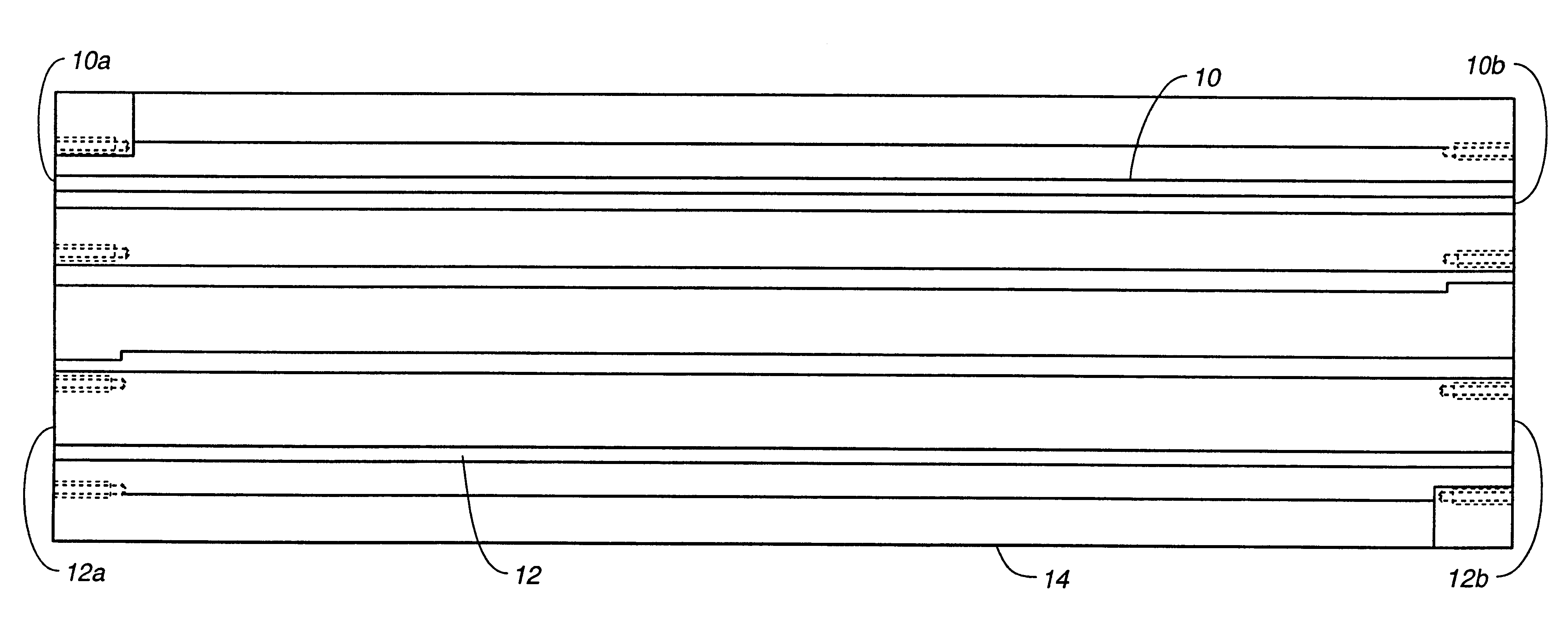
FIG. 1 is a top plan view of a pair of magnet arrays 10, 12 forming a dual race track magnet structure 14 for the improved apparatus of this invention. Placement of the second magnet array or "race track" 12 adjacent the first magnet array or "race track" 10 reduces the power density on the target surface by approximately fifty percent (relative to a single "race track" configuration). In this embodiment, the respective arrays 10, 12 are of equal overall length, immediately adjacent to each other, and not offset, so that the respective ends 10a, 12a and 10b, 12b are aligned.

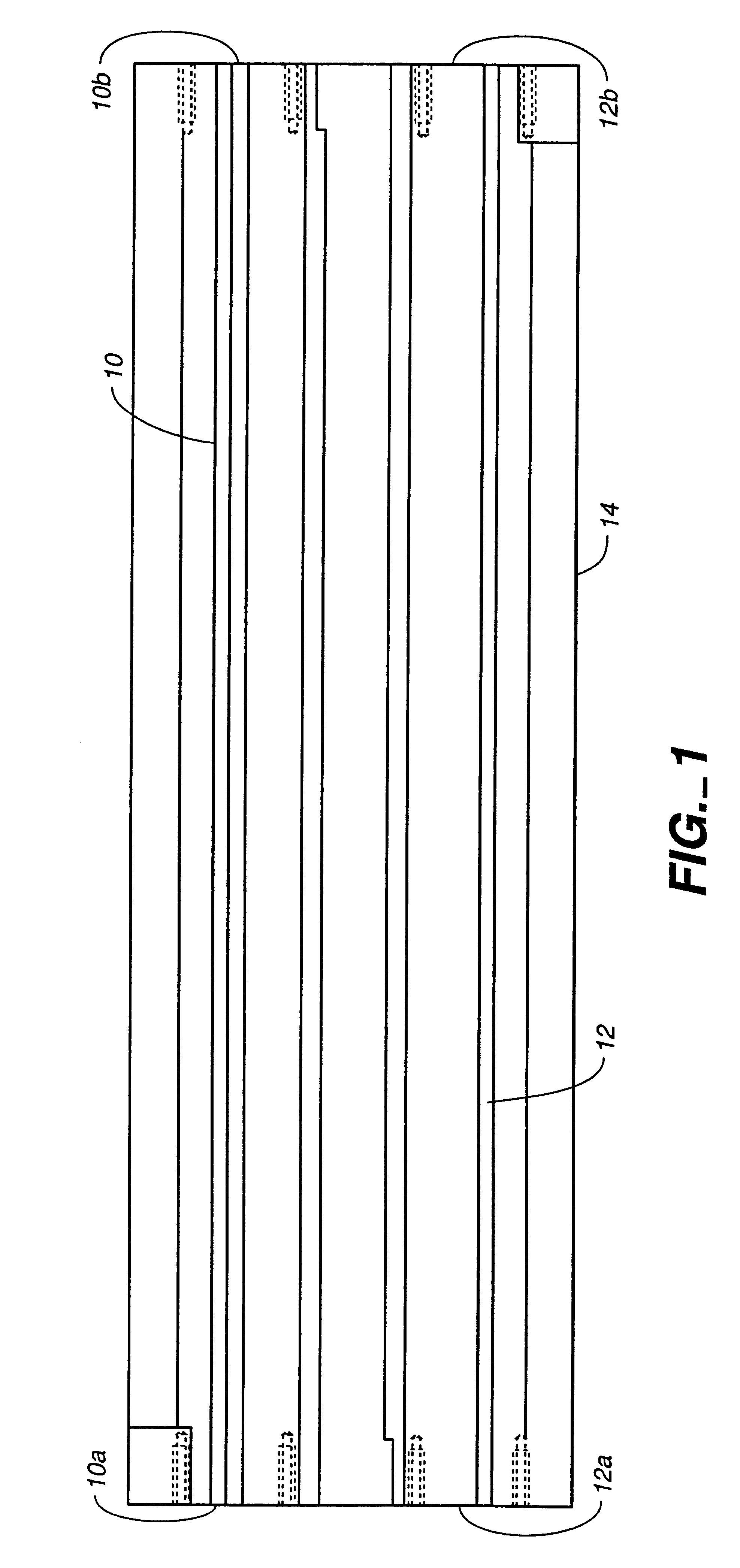
FIG. 2 is a cutaway top plan view of one end of a pair of offset magnet arrays 20, 22 forming an offset dual race track magnet structure 24, the other end being a mirror image. The amount of the longitudinal offset 26 between the end 20a of magnet structure 20 and the end 22a of magnet structure 22 is preferably approximately two times the width W of the end magnet(s) 28, or 2:1. For example, if end magnet 28 has...


PUM

PropertyMeasurementUnit
Fractionaaaaaaaaaa
Thicknessaaaaaaaaaa
Lengthaaaaaaaaaa

Abstract

Material utilization and process stability for a rotating cylindrical magnetron target used in a sputtering system are improved by incorporation of a second magnet structure or "race track", allowing the power density on the target surface to be reduced by approximately 50% for any given point where magnetic confinement of the plasma exists. Offsetting one race track relative to the other along the longitudinal axis of the target reduces the power density at each turn-around area (relative to the longitudinal area). Modestly increasing the target material thickness at the ends of the target allows nearly all of the material between the turn-around areas to be sputtered.

Description

1. Field of the InventionThis invention relates generally to a rotating cylindrical magnetron apparatus, and more specifically to the magnetic structure or array used to provide a magnetic field or "race track" to sputter the material contained on the surface of the cylindrical magnetron target, and the configuration of the target material relative to the magnetic structure.2. Description of the Prior ArtThis invention relates directly to an apparatus used for magnetron sputtering utilizing rotating, cylindrical shaped targets (cathodes). The cylindrical targets are used to deposit various materials onto a variety of substrates. The materials are deposited in a vacuum chamber using a gas reactive magnetron sputtering technique. The principles and operation of such apparatus are described in detail in Boozenny et al. U.S. Pat. No. 5,096,062, describing a large-scale cylindrical sputtering apparatus (sold by Airco Coating Technology under the trademark "C-MAG") used for sputtering coa...

Claims


Application Information

Patent Timeline
IPC IPC(8): C23C14/35H01J37/32H01J37/34
CPCH01J37/3405C23C14/35
Inventor MORGAN, STEVEN V.VANDERSTRAETEN, JOHANVANDERSTRAETEN, ERWINGOBIN, GUY
Owner BVBA EMIEL VANDERSTRAETEN
Why Eureka
Try Eureka