
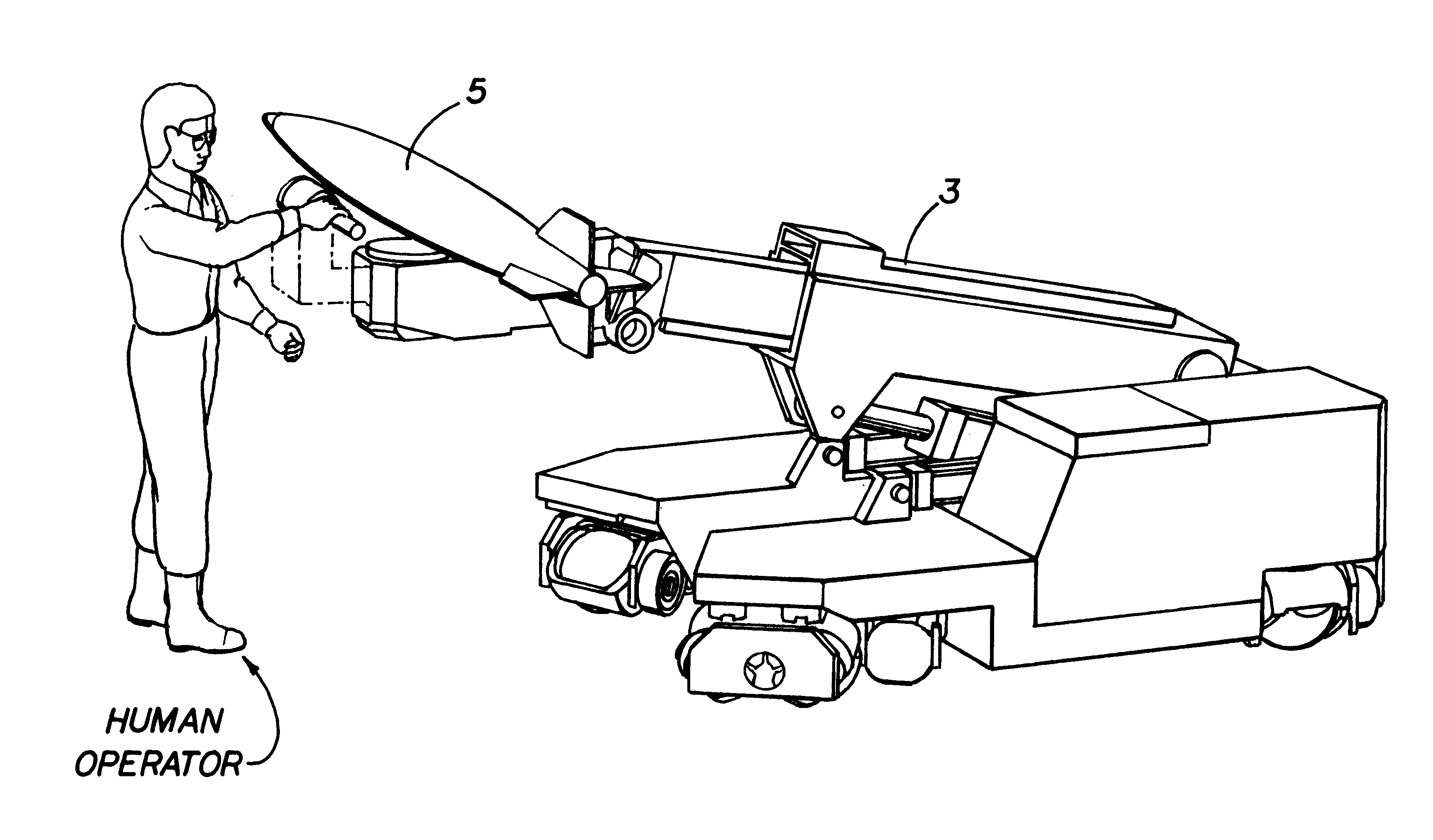
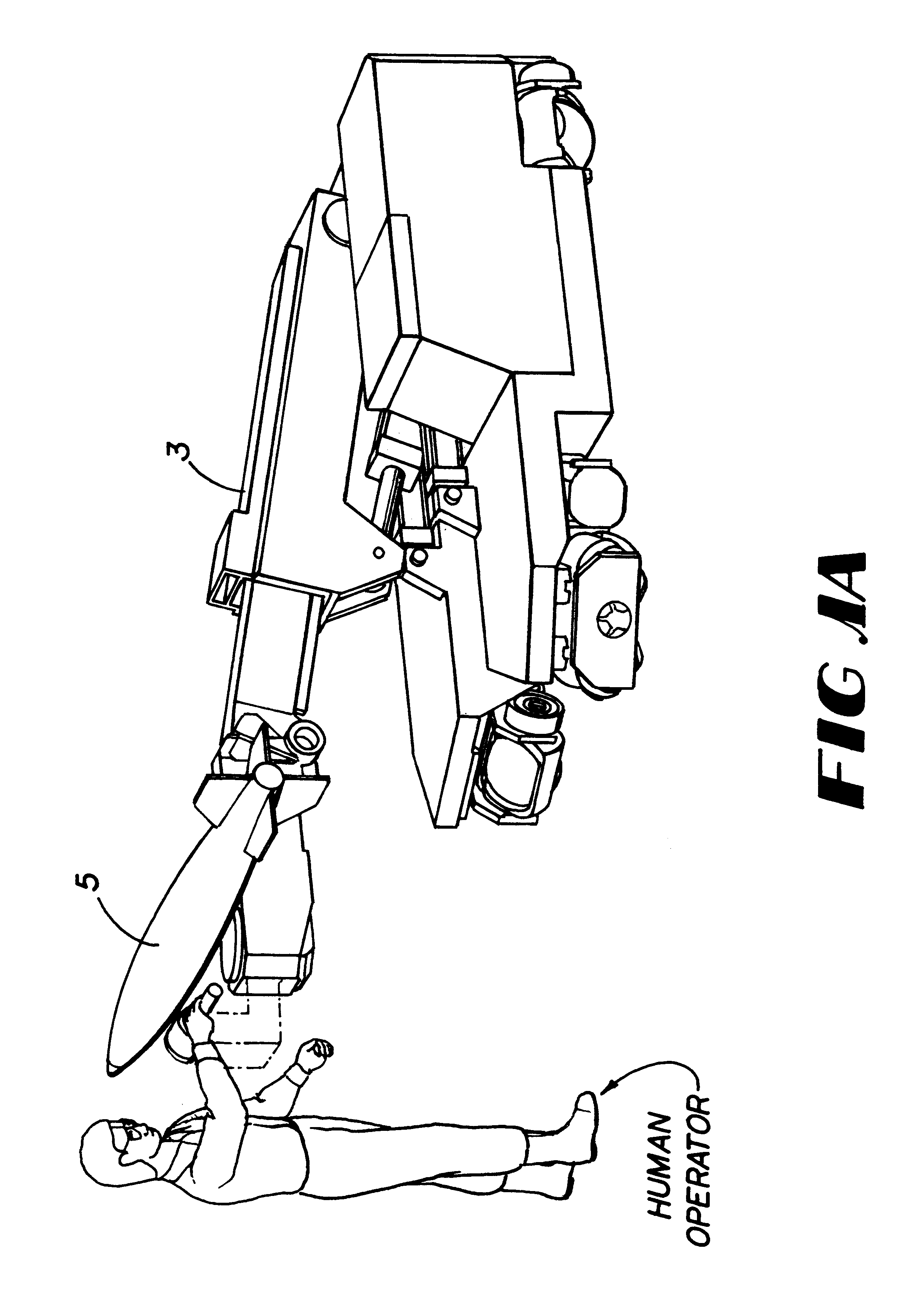
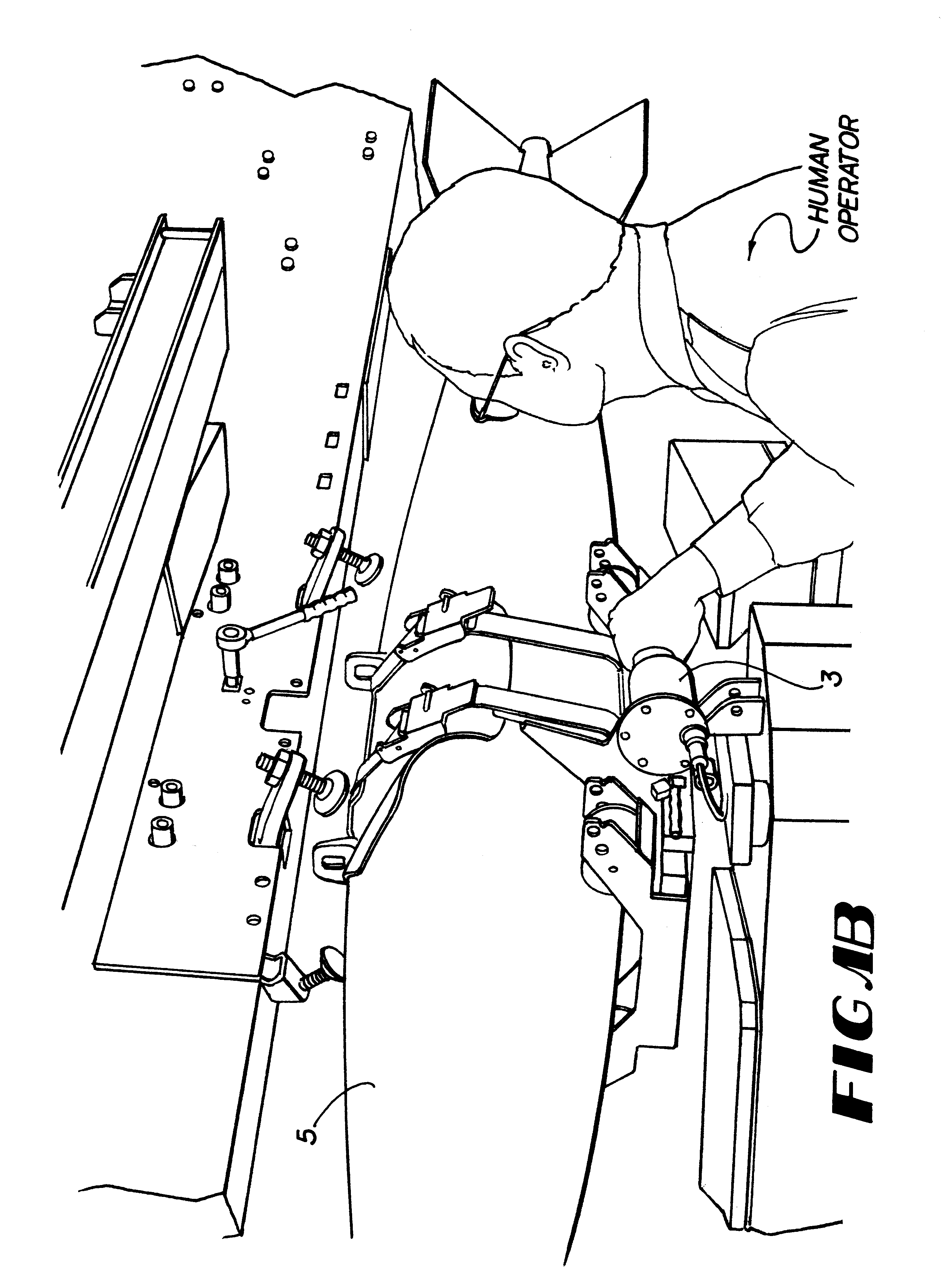
Apparatus and methods for a human extender

a human extender and apparatus technology, applied in the field of apparatus and methods for human extenders, can solve the problems of a significant computational burden on the controller, the inability to best perform tasks by a traditional robot manipulator, and the availability of human amplifier systems

Inactive Publication Date: 2001-08-14
LOCKHEED MARTIN ENERGY SYST INC
View PDF5 Cites 34 Cited by
  • Summary
  • Abstract
  • Description
  • Claims
  • Application Information

AI Technical Summary

Problems solved by technology

These tasks cannot be best performed by a traditional robot manipulator because these tasks need a spontaneous information signal and power transfer between the human operator and the working environment, which cannot be provided by the traditional robot manipulator with a master-slave design.
However, a number of problems associated with the available human amplifier systems.
Unfortunately, computed torque technique is a model based scheme that requires significant knowledge about the physical system plus it represents a significant computational burden on the controller.
Computed torque can be rendered basically useless if the model is just a few percent off of the calculated value.
Because of these problems, the current human extenders have very limited payload capacities and limited force reflection ratios under 19 to 1 as discussed in the paper "Human Extenders," Kazerooni, H., J. Guo, Journal of Dynamic Systems, Measurement, and Control, Vol. 115, pp.
This system is deficient for tasks that require forces in both the upward and downward directions or if forces and moments are required in other planes of motion.
Although very well designed, the Jammer systems require a three-person crew and for certain loading conditions the turn-around time can sometimes rise dramatically.
However, if the manipulator has more degrees-of-freedom then required to perform a task (i.e., it is mechanically redundant) then the inversion process optimizes some performance criteria.
Furthermore, slow to moderate manipulator speeds are typical when large payloads are manipulated.

Method used


Image

  • Apparatus and methods for a human extender
  • Apparatus and methods for a human extender
  • Apparatus and methods for a human extender

Examples


Embodiment Construction

Shown in FIG. 5

Two transfer functions can be obtained from FIG. 5. The first is the transfer function from the force at the hand, F.sub.hand, to the actuator velocity , y, with the external force due to the contact, F'.sub.ext, set to zero

.sup.y T.sub.F.sub..sup.hand =[K.sub.amp K.sub.cli G.sub.comp (K.sub.q / A)] / [s(s.sup.2 / .omega..sub.h.sup.2 +2s.xi..sub.eq / .omega..sub.h +1)+MK.sub.cli G.sub.comp (K.sub.q / A)(s+a.sub.v)] (1)

with the assumptions that the load will be a constant load and not a spring type load (i.e., .omega..sub.ext =0). The second transfer function is the one that relates the external force due to contact , F'.sub.ext, to actuator velocity, y, with the force at the hand, F.sub.hand, set to zero

.sup.y T.sub.F'.sub..sup.ext =(-1 / M)[s(s.sup.2 / .omega..sub.h.sup.2 +2s.xi..sub.eq / .omega..sub.h +MK.sub.cli G.sub.comp (K.sub.q / A)] / [s(s.sup.2 / .omega..sub.h.sup.2 +2s.xi..sub.eq / .omega..sub.h +1)+MK.sub.cli G.sub.comp (K.sub.q / A)(s+a.sub.v)] (2)

with the assumption that...


PUM

PropertyMeasurementUnit
forcesaaaaaaaaaa
forceaaaaaaaaaa
contact forceaaaaaaaaaa

Abstract

A human extender controller for interface between a human operator and a physical object through a physical plant. The human extender controller uses an inner-feedback loop to increase the equivalent damping of the operating system to stabilize the system when it contacts with the environment and reduces the impact of the environment variation by utilizing a high feedback gain, determined by a root locus sketch. Because the stability of the human extender controller of the present invention is greatly enhanced over that of the prior art, the present invention is able to achieve a force reflection ratio 500 to 1 and capable of handling loads above the two (2) ton range.

Description

1. Field of the InventionThe present invention comprises an apparatus and methods for a human extender. In particular, the invention relates to an apparatus and methods for a human extender controller capable of interfacing a human operator and a physical object so that the physical object can be dexterously manipulated.2. Background ArtA human extender is a device that amplifies the lifting capacity of a human operator and allows a preselected amount of force feedback to the operator (i.e., the operator can feel part of the load). This type of system is fundamentally different from a teleoperator system because the master and slave manipulators are a single unit in a human extender. This concept was first developed in the 1960's by General Electric during the Hardiman project, as documented in the publications of "Special Interim Study, Hardiman I Prototype Project," Report S-68-1060, General Electric Company, Schenectady, N.Y., Apr. 19, 1968, "Hardiman I Arm Test, Hardiman I Proto...

Claims


Application Information

Patent Timeline
Patent Type & Authority Patents(United States)
IPC IPC(8): B62D51/04B62D51/00B66C13/18
CPCB62D51/04B66C13/18
Inventor JANSEN, JOHN F.
Owner LOCKHEED MARTIN ENERGY SYST INC
Learn More