Oxide gas absorbing arrangement and method

a technology of absorbing arrangement and absorbing material, which is applied in the direction of arsenic compounds, silicon compounds, separation processes, etc., can solve the problems of large emission, no long-term high temperature condition such as is required to regenerate the absorber, and limited use, etc., to achieve good long-term stability of the absorber

Inactive Publication Date: 2001-08-14
VOLKSWAGEN AG
View PDF11 Cites 32 Cited by
  • Summary
  • Abstract
  • Description
  • Claims
  • Application Information

AI Technical Summary

Benefits of technology

is to provide an absorber for nitrogen oxides and a corresponding method, suitable especially for use with fuel consumption-optimized engines such as Diesel and / or direct injection Otto engines, in which regeneration of the absorber is possible even at low exhaust gas temperatures.
Since the release and conversion of the NO.sub.x from the storage layer and the release of the oxides of sulfur from the storage layer require different temperatures, higher in the case of the sulfur oxides, it is also possible to proceed so that a desorption of the oxides of sulfur, which are present in particular as sulfate is performed at longer time intervals or only as needed, so that the storage layer is only occasionally heated to the high temperatures needed for desorption of the sulfur oxides. This counteracts premature aging of the storage layer, so that an especially good long-term stability of the absorber is achieved. This procedure may be used with the absorber arrangement and method described above.

Problems solved by technology

In this case, however, the possibility of use is limited since, under certain operating conditions of internal combustion engines, such as occur for example in city traffic, the acceleration phases cause a large emission of nitrogen oxide, but no long-lasting high temperature condition such as is required to regenerate the absorber, especially with respect to oxides of sulfur, is attained.
Further, by heating the absorber such as electrically or by means of a burner, a soot deposit on the absorber which would otherwise definitely reduce the storage capacity can be burned off.

Method used


Image

  • Oxide gas absorbing arrangement and method
  • Oxide gas absorbing arrangement and method

Examples


Embodiment Construction

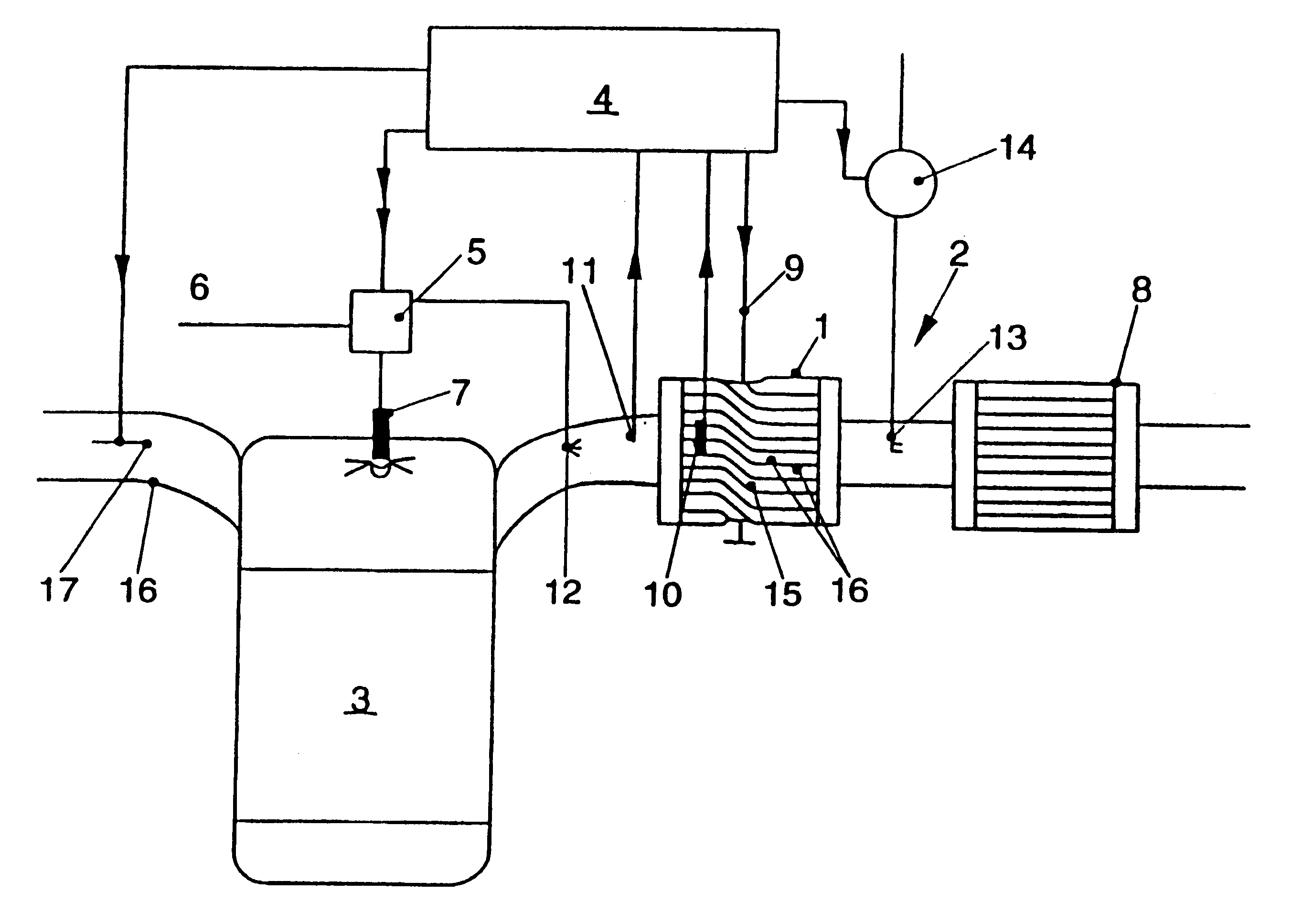
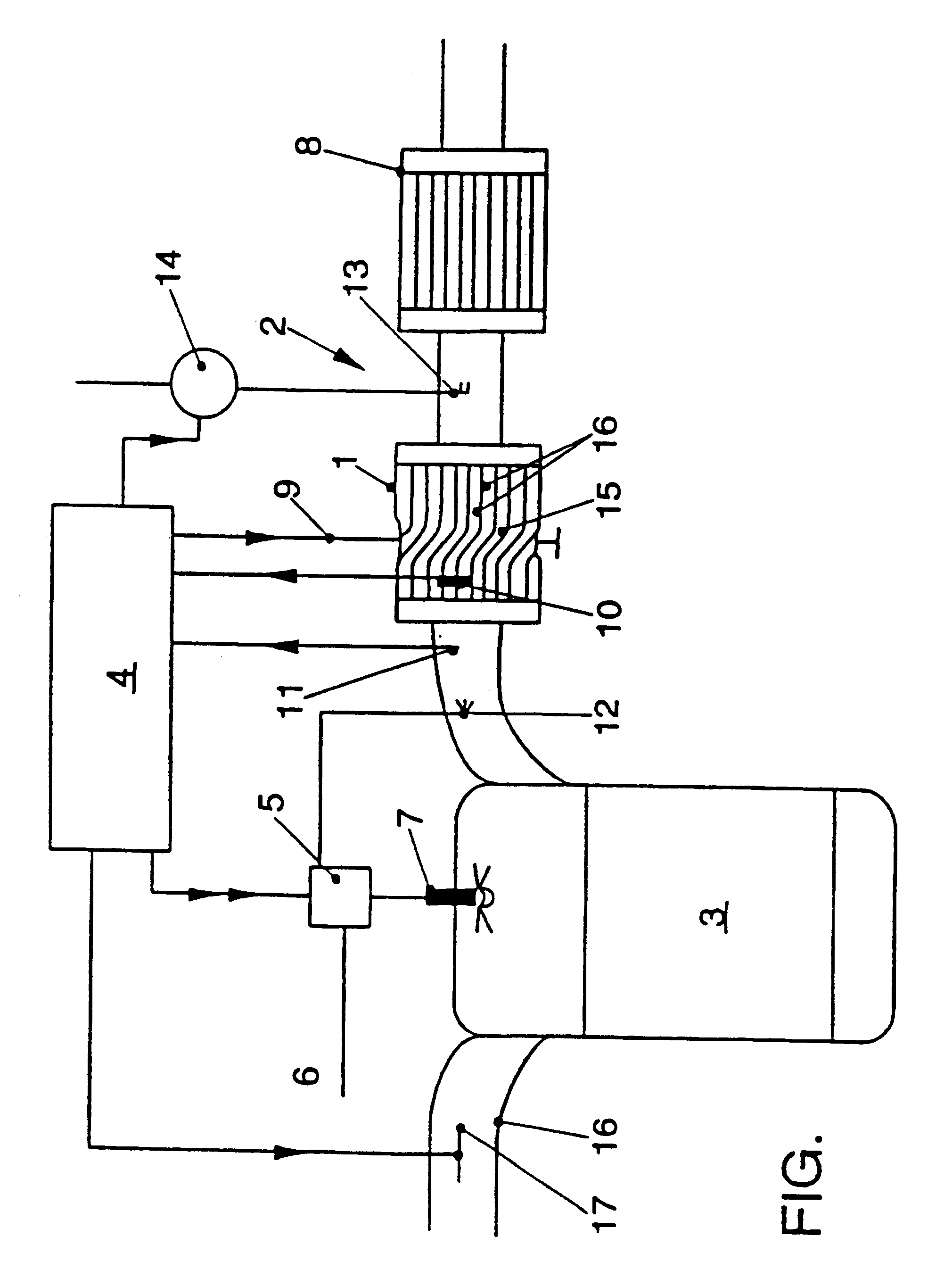
In the typical embodiment of the invention shown in the drawing an absorber 1 of oxide gas components is mounted in an exhaust line 2 of an internal combustion engine 3 the operation of which is controlled by a motor control unit 4. The motor control unit 4 controls an injection pump 5 delivering fuel from a tank 6 (not shown) to a fuel injection nozzle 7. For the sake of clarity, the numerous conventional control lines for fuel and air supply and discharge and the like leading to the motor control unit 4 are not shown.

In the illustrated exhaust line 2 a three-way catalyst 8 is mount downstream from the absorber 1 but it is also possible to locate the three-way catalyst 8 upstream from the absorber 1.

In this embodiment, the absorber 1 is made from two metal foils one of which is smooth and the other of which is corrugated and is connected to the smooth foil by soldering at the corrugation crests. By rolling this multilayer foil together, a cylindrical member having a plurality of co...


PUM

PropertyMeasurementUnit
thicknessaaaaaaaaaa
temperatureaaaaaaaaaa
diametersaaaaaaaaaa

Abstract

In the oxide gas absorbing arrangement disclosed in the specification, metal foils having a thickness <=0.05 mm are coated with an oxide gas absorbing layer containing gamma aluminum oxide. One metal foil is corrugated and joined to a smooth foil and the combined foils are rolled into a cylinder to provide parallel gas passages in which exhaust gases are exposed to the oxide gas absorbing layer. To enhance absorption turbulence is created in the gas passages by twisting the cylinder to narrow and contort the individual passages.

Description

BACKGROUND OF INVENTIONThis invention relates to absorbing arrangements and methods for temporarily storing oxides of nitrogen and sulfur and removing such oxides from the exhaust gas from internal combustion engines.As used herein, the term "absorb" includes the chemical process for storing gases such as, for example, by conversion of barium oxide to barium nitrate for storage of nitrogen oxide.U.S. Pat. No. 4,755,499 discloses an arrangement for the reversible storage of oxides of nitrogen and sulfur, for example from motor vehicle exhaust gases, in which the absorber is regenerated by heating in a reducing atmosphere. In this arrangement, a reduction of the nitrogen oxides takes place at the same time.A storage catalyst of that type for use in motor vehicles is described in more detail in U.S. Pat. No. 5,402,641, in which high temperatures above 500.degree. C. are necessary to regenerate the absorber. Consequently, use of the storage catalyst is possible only for motor vehicles h...

Claims


Application Information

Patent Timeline
Patent Type & Authority Patents(United States)
IPC IPC(8): B01D53/04B01D53/94F01N3/08F01N3/22F01N3/20F01N7/00F01N7/02F02B1/00F02B1/04B01D53/60B01D53/74B01D53/86F01N3/10F01N3/28F01N13/02
CPCB01D53/0415F01N13/009B01D53/9481B01D53/949F01N3/0814F01N3/0842F01N3/085F01N3/0871F01N3/0885F01N3/22F01N3/222B01D2251/304B01D2251/408B01D2251/60B01D2253/25B01D2253/34B01D2257/302B01D2257/404B01D2258/01B01D2259/40009B01D2259/40096B01D2259/4566F01N2240/16F01N2250/12F01N2610/03F02B1/04Y02T10/22B01D53/0454Y02T10/12B01D53/94B01D53/56B01D53/02
Inventor HELD, WOLFGANG
Owner VOLKSWAGEN AG
Why Eureka
Try Eureka