
Processor powerdown operation using intermittent bursts of instruction clock

a technology of instruction clock and power supply, which is applied in the direction of memory address/allocation/relocation, instruments, liquid/fluent solid measurement, etc., to achieve the effect of reducing the frequency of instruction clock, preventing communication with unused processing devices, and prolonging the useful life of portable devices

Inactive Publication Date: 2001-08-14
AGERE SYST INC
View PDF10 Cites 34 Cited by
  • Summary
  • Abstract
  • Description
  • Claims
  • Application Information

AI Technical Summary

Benefits of technology

In accordance with the disclosed embodiment of the present invention, the instruction clock of a processing unit in a low power mode in accordance with the principles of the present invention is qualified with a burst mode control signal. The burst mode control signal is allowed to start and stop the instruction flow of the relevant processing unit. As a result, the low power mode processing unit's average number of executed instructions per second is reduced to reduce the overall power consumption of the processing unit, yet the executed instructions are performed at full rate.

Problems solved by technology

The lower power the processing unit, the longer the useful life of the portable device and / or the smaller the required battery.
However, these techniques either prevent communication with the unused processing devices, or require the processing device to power up to receive the communications.
However, reduction of the frequency of the instruction clock in a processing unit typically requires cumbersome circuitry to stretch the master clock signal, and slows communications between powered-down devices and fully operating devices, detrimentally affecting the application program(s) running on the full-rate devices.

Method used


Image

  • Processor powerdown operation using intermittent bursts of instruction clock
  • Processor powerdown operation using intermittent bursts of instruction clock

Examples


Embodiment Construction

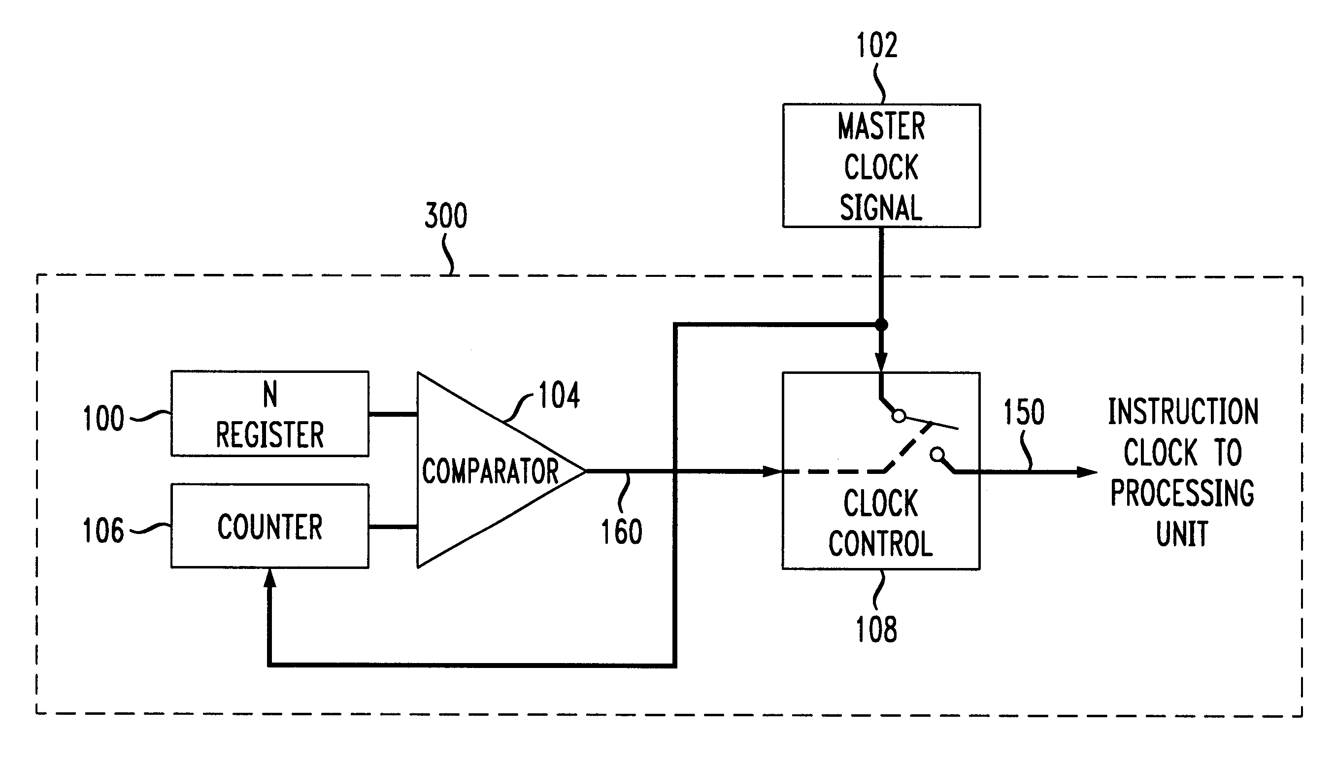
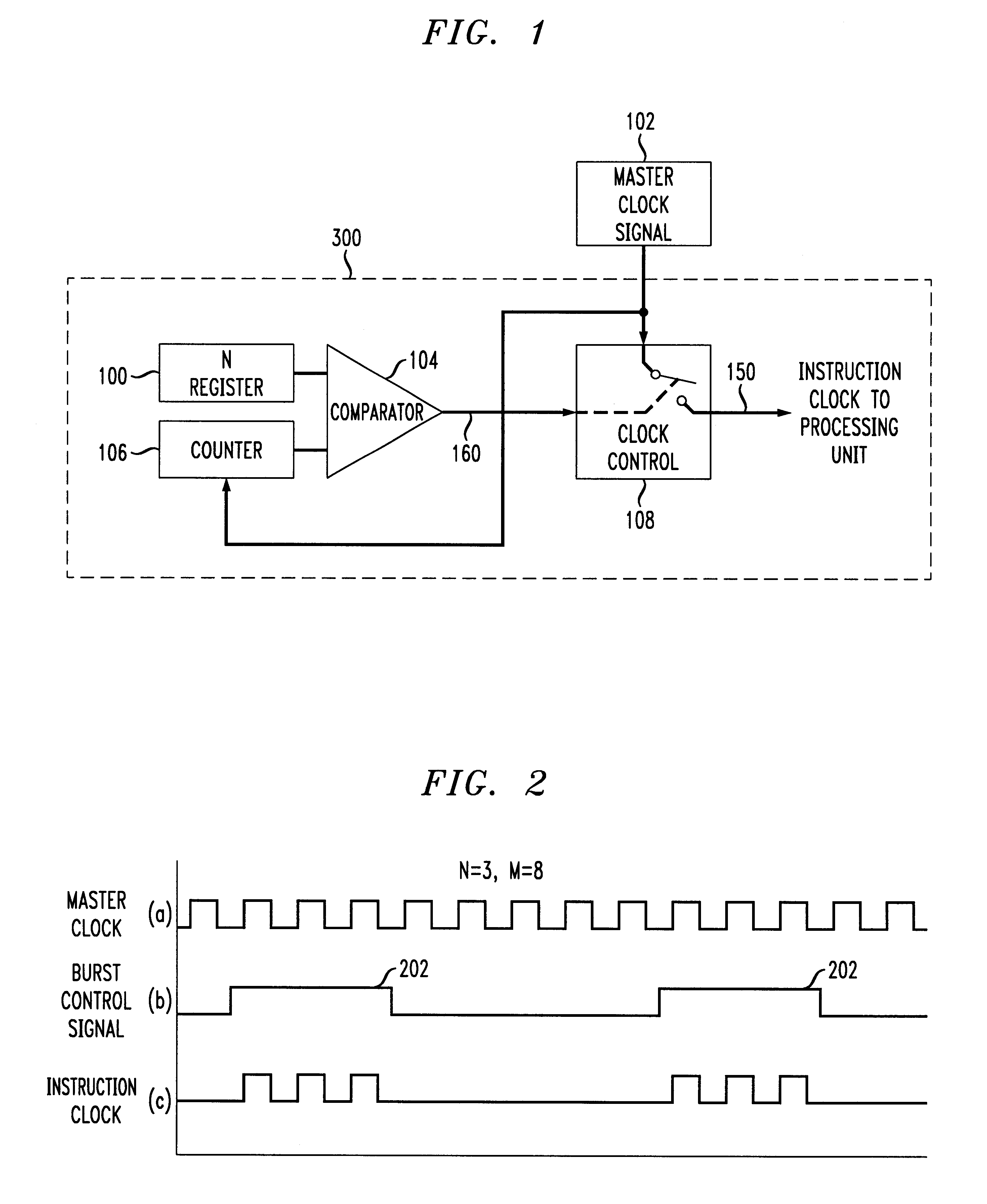
The present invention provides a method and apparatus for reducing the power dissipation of a processing unit by providing intermittent full rate bursts of the instruction clock of the processing unit. The processing unit may be, e.g., a microprocessor, a microcontroller, a digital signal processor (DSP), and / or a host controller.

In accordance with the disclosed embodiment of the present invention, the instruction clock of a processing unit in a low power mode in accordance with the principles of the present invention is qualified with a burst mode control signal. The burst mode control signal is allowed to start and stop the instruction flow of the relevant processing unit. As a result, the low power mode processing unit's average number of executed instructions per second is reduced to reduce the overall power consumption of the processing unit, yet the executed instructions are performed at full rate.

FIG. 1 illustrates one exemplary implementation of a burst instruction cycle con...


PUM


Abstract

An instruction clock of a processing unit in a low power mode in accordance with the principles of the present invention is qualified with a burst mode control signal. The burst mode control signal is allowed to start and stop the instruction flow of the relevant processing unit. In the disclosed embodiment, a master clock signal is qualified by a clock control circuit to provide bursts of an instruction clock signal to the relevant processing unit. To operate the burst instruction cycle control unit, a user pre-programs a burst length, into a register to set the length of the burst of instruction cycles to the relevant processing unit. A maximum counter value in a counter sets the period of the instruction cycle bursts provided to the relevant processing unit. As long as the current value of the counter is less than or equal to the pre-programmed burst length, the burst control signal allows a clock controller to pass a master clock signal or other relevant clock signal as an instruction clock signal to the relevant processing unit. The low power burst mode and thus the power savings is adjustable according to the combined values of burst length and maximum counter value.

Description

1. Field of the InventionThis invention relates generally to the reduction of power usage by processing units. More particularly, it relates to the reduction of power usage by a processing unit while allowing the clock cycles of the processing unit to occur at full rate.2. Background of Related ArtThe increasing use of portable devices has generated a need in the industry for low power processing units. The lower power the processing unit, the longer the useful life of the portable device and / or the smaller the required battery.Moreover, continued integration of devices has generated an environment wherein multiple processing units or other devices perform separate tasks but in coordination with one another. Oftentimes, the processing units and / or other devices communicate based on common timing or within certain time frames. Conventionally, a continuously operating master clock is typically required to maintain communications between the separate devices or circuits.One common tech...

Claims


Application Information

Patent Timeline
Patent Type & Authority Patents(United States)
IPC IPC(8): G06F1/32H04L7/00H04L7/02G06F11/34G06F12/06
CPCG06F1/3203G06F1/3237G06F11/349G06F12/0646Y02B60/165H04L7/0025H04L7/0029Y02B60/1221H04L7/0004H04L7/0278Y02D10/00
Inventor BAYS, LAURENCE E.FADAVI-ARDEKANI, JALILFITCH, KENNETH DANIELNIESCIER, RICHARD JOSEPH
Owner AGERE SYST INC
Learn More