Impeller manufacturing process

Inactive Publication Date: 2001-08-21
FLOWSERVE MANAGEMENT CO
View PDF13 Cites 78 Cited by
  • Summary
  • Abstract
  • Description
  • Claims
  • Application Information

AI Technical Summary

Benefits of technology

A feature of this method of manufacturing an impeller is that the components are mated to one another, and thus their contacting surfaces fit together tightly, without significant voids between them. This is important to strengthen the subsequent connection between the portions, by providing the contacting surfaces to be at a relatively fixed distance from one another, allowing for proper welding or other connection.
Another feature of this method is that the components may be individually machined, reducing the cost and time for such operation.
Another feature of this method is that the overall cost is reduced, as no casting or molding of the vanes is necessary. Economical machining is used, and there is no need for further deformation, or for expensive machinery to finish and align the components.
Another feature of this method is that because the components are mated with one another, when they are placed in the correct radial position the components self-align relative to one another. Thus the contacting surfaces are precisely aligned, and can be brazed rather than welded, providing a tight fit without gaps.
Another feature of this method is that the upper and lower surfaces of the vanes, which will mate with the shroud and hub respectively, are machined when the core is a single component, reducing the time and expense which would be required to individually machine the upper and lower surface of each vane, and increasing the precision of the mating surfaces.

Problems solved by technology

Both the use of a five-axis machine, and the process of electron-beam welding are quite expensive and require long lead times for production.
Further, this method of fabricating impellers allows the potential for crevice erosion, since electron beam welding does not make a complete joint from one side of each vane to the other.
There is also the potential for poor mating between the hub-vanes portion of the impeller and the shroud portion of the impeller, since the respective surfaces of the shroud and vanes that are in contact with each other may not match up, and the intersection of the surfaces may leave gaps between them.
In addition to allowing voids or gaps between the surfaces, when the shroud and the vanes are not specifically matched to one another, there is a likelihood of improper or imprecise alignment.
Finally, the cost of machining, assembling and welding the shroud and hub-vanes portions of the impeller, first utilizing a five-axis machine and then subsequently electron-beam welding the portions together is very high, both from a monetary and a time-management viewpoint.

Method used


Image

  • Impeller manufacturing process
  • Impeller manufacturing process
  • Impeller manufacturing process

Examples


Embodiment Construction

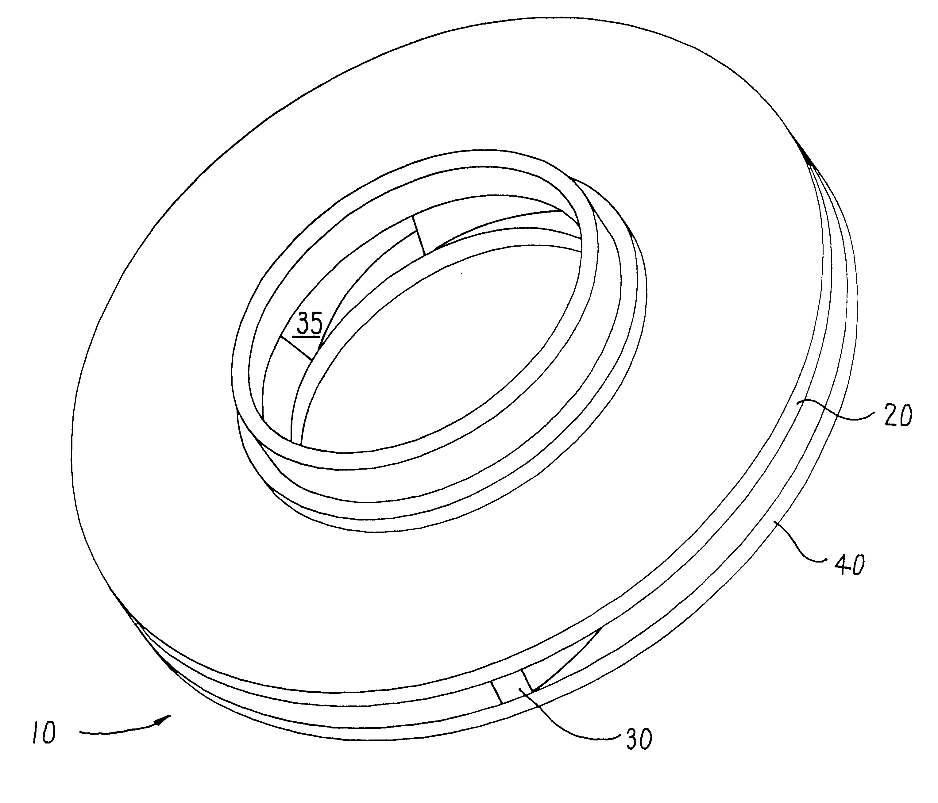
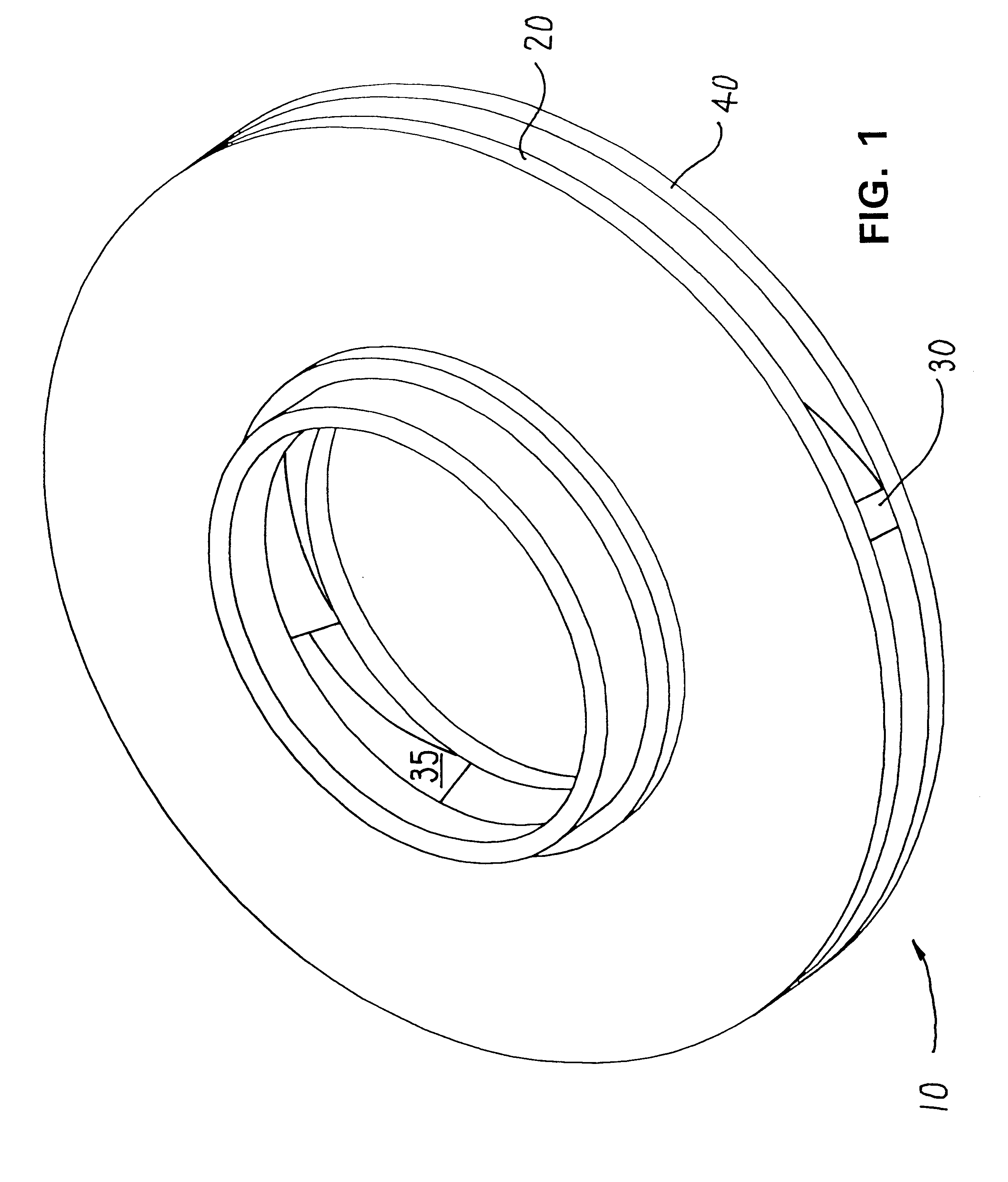
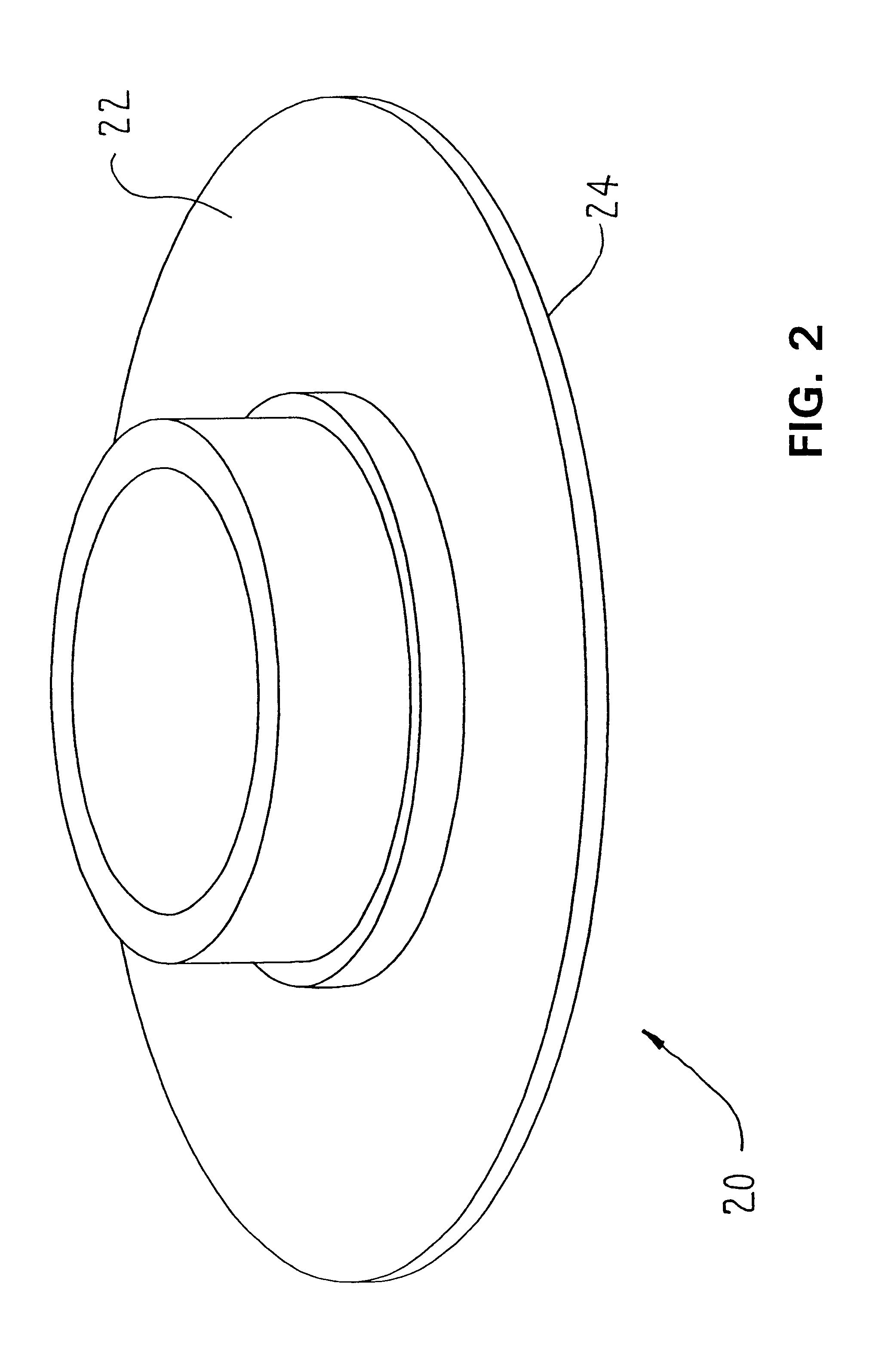
As illustrated in FIGS. 1-4, the impeller 10 includes three portions--a shroud 20, a core 30, and a hub 40. These portions are individually machined.

The core 30 has a first surface 32, and a second surface 34. The shroud 20 has a first surface 22 and a second surface 24. The hub has a first surface 42 and a second surface 44.

The first surface 32 of the core 30 and the second surface 24 of the shroud 20 are machined to define surfaces which will mate with one another. Preferably, this machining is done by turning the parts on a CNC lathe. However, it will be appreciated by those skilled in the art that any other machining techniques or devices which provide the necessary precision may also be used. Similarly, the second surface 34 of the core 30 and the first surface 42 of the hub 20 are machined to define surfaces which will mate with one another. In a preferred embodiment, the respective mating image surfaces 32, 24 and 34, 42 define complex contours specified by hydraulic drawings...


PUM

PropertyMeasurementUnit
Weightaaaaaaaaaa
Diameteraaaaaaaaaa

Abstract

A method of manufacturing an impeller, comprising machining hub, shroud and core portions, such that contacting surfaces between the hub and core, and shroud and core form mating surfaces, for mating and alignment with each other. Material is removed from the core without disturbing the contour of its surfaces, resulting in one or more vanes which mate with the respective hub and shroud portions. The mating portions are then coupled together.

Description

BACKGROUND OF THE INVENTIONThis invention relates to impellers for centrifugal pumps, and more specifically to a process for manufacturing impellers.A pump impeller is composed essentially of three parts: a hub portion, vanes, and a shroud portion. Traditionally, there have been several ways to manufacture impellers. In one method, molds for the vanes are placed on top of a hub. The molds are arranged as desired for the vanes, and filled with weld material. The material fills the mold, forms the vanes, and is attached to the hub. The shroud must then be attached to the vanes.Several other manufacturing methods use pre-fabricated vanes, which are then welded in place between the hub and the shroud. In another method, a set of long vanes are attached to the hub, extending from the edge to the center. A set of shorter blades which do not extend all the way to the center of the hub are attached to the shroud. The complementary hub and shroud are then attached, with the vanes interleaved...

Claims


Application Information

Patent Timeline
IPC IPC(8): B23P15/00F01D5/02F01D5/04F04D29/22F04D29/18
CPCB23H9/10B23P15/006F01D5/048F04D29/2222Y10T29/4932F05D2230/10F05D2230/61
Inventor LAMBERT, TOMPIATT, RAY
Owner FLOWSERVE MANAGEMENT CO
Why Eureka
Try Eureka