Heat exchange method and apparatus

a technology of heat exchange apparatus and heat exchange method, which is applied in the direction of indirect heat exchangers, sorption machines, climate change adaptation, etc., can solve the problems of large amount of waste fluids and gases, lack of heat recovery mechanism, and inability to heat recovery, so as to reduce the size of the absorption chiller, improve the heat transfer in the cooling system, and promote the absorption of vapor.

Inactive Publication Date: 2001-09-04
DISTRIBUTED POWER SYST
View PDF8 Cites 34 Cited by
  • Summary
  • Abstract
  • Description
  • Claims
  • Application Information

AI Technical Summary

Benefits of technology

One embodiment of the present invention is a heat exchanging method and apparatus for improving heat transfer in a cooling system. Specifically, the heat exchanging method and apparatus is an absorption chiller having a generator section, a condenser section and an evaporator section. Disposed within these three sections is a heat transfer device having a first heat pipe partially disposed within a second heat pipe, where the juncture of the coupled heat pipes promotes absorption of a vapor into a working solution. More specifically, the juncture of the coupled heat pipes is disposed within the condenser section such that two processes, condensation and absorption of the absorption chiller are efficiently implemented within a single section or chamber, i.e., elimination of the need for a separate absorber section as in prior art absorption chillers. The ability to implement the absorber function using the heat pipes within the condenser provides advantages that, include but are not limited to, a reduction in the size of the absorption chiller and an increase in the overall thermal efficiency, where the cooled water of the condenser is also exploited to absorb the heat generated from the recombination process.

Problems solved by technology

Furthermore, over 70% of this energy is currently provided by a limited supply of hydrocarbon fuels.
Traditionally, many of the processes and techniques for accomplishing these three functions generate an enormous amount of waste fluids and gases.
Generally, these waste products retain a large quantity of energy in the form of heat which, upon release, contributes to the problem of global warming.
The waste heat is also indicative of the thermal inefficiency of these processes and the lack of a heat recovery mechanism.
The waste water often retains a significant amount of recyclable heat that is simply released into the environment.
The discharge of heated waste water represents the thermal inefficiency of these processes.

Method used


Image

  • Heat exchange method and apparatus
  • Heat exchange method and apparatus
  • Heat exchange method and apparatus

Examples


Embodiment Construction

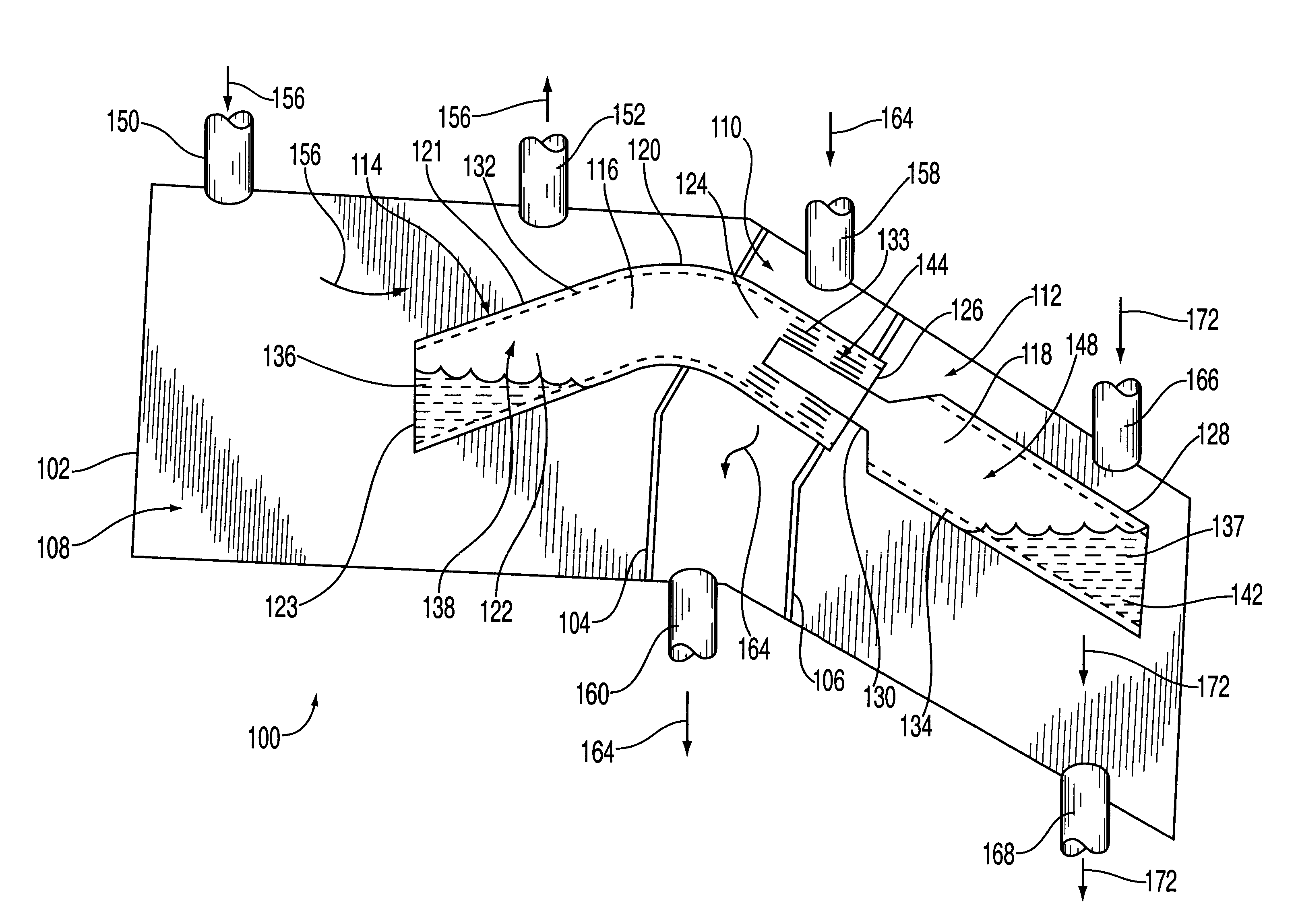
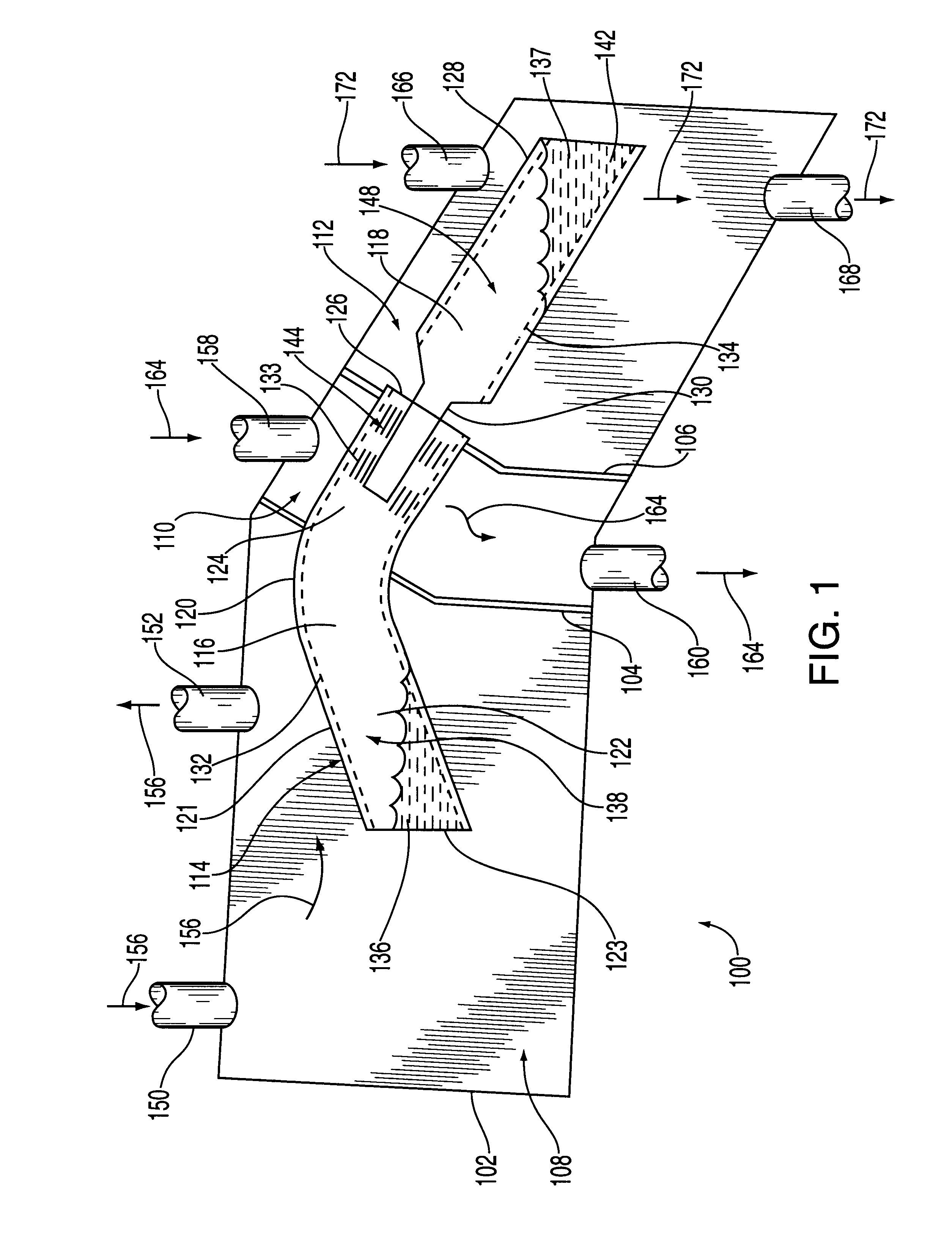
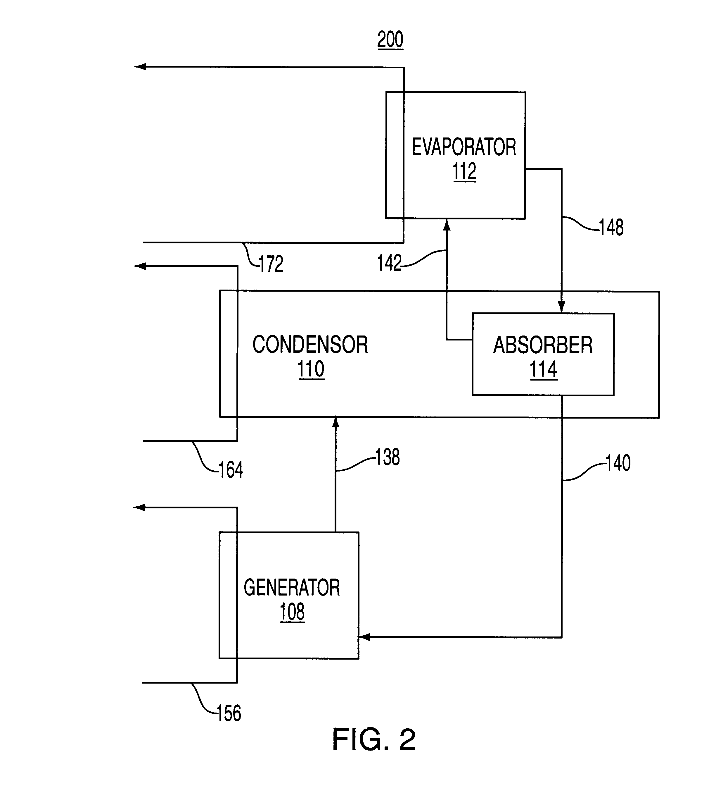
In a preferred embodiment, a heat exchanger, or absorption chiller 100 of the present invention is depicted in FIG. 1. The absorption chiller 100 has a housing 102 fabricated from any structurally stable material, preferably metal or plastic. The absorption chiller 100 has a first bulkhead 104 and a second bulkhead 106 that segment the absorption chiller 100 sequentially into a generator 108, a condenser 110 and an evaporator 112. The generator 108, condenser 110 and evaporator 112 are all sealed from one another.

Disposed within the three chambers or sections of the absorption chiller 100 is a heat transfer device or means 114 that comprises a pair of interlocking "heat pipes" carrying working fluids. In brief, the purpose of the pair of interlocking heat pipes is to effect heat transfer between the various chambers of the absorption chiller 100 and the working fluids of the heat pipes. As a result of a plurality of heat transfer cycles between the heat pipes and the various chamber...


PUM


Abstract

A heat exchanging method and apparatus for improving heat transfer in a cooling system. Specifically, the heat exchanging method and apparatus is an absorption chiller that comprises a heat transfer device having one heat pipe partially disposed within a second heat pipe, where the juncture of the coupled heat pipes promotes absorption of a vapor into a working solution. The juncture of the coupled heat pipes is disposed within a condenser section such that two processes, condensation and absorption of the absorption chiller are efficiently implemented within a single section or chamber.

Description

BACKGROUND OF THE DISCLOSURE1. Field of InventionThe present invention relates generally to a heat exchange apparatus. More specifically, the invention relates to an apparatus for propelling a process within an "absorption chiller" for providing cooled water to a cooling system, e.g., a central air conditioning system. A heat source, e.g., heated water, is used to release a refrigerant from a lithium bromide solution where the condensed refrigerant is used to cool water for a central air conditioning system. Specifically, the present invention comprises a two-pipe configuration where a first pipe is partially disposed within a second pipe, wherein the coupled portions of the two pipes promote efficient heat exchange, thereby improving the efficiency of the absorption chiller.2. Description of the Background ArtCurrently, it is estimated that space heating, water heating and industrial process heating account for approximately 40% of all energy consumption in the industrialized natio...

Claims


Application Information

Patent Timeline
Patent Type & Authority Patents(United States)
IPC IPC(8): F25B15/02F25B15/06F25B33/00F28D15/02
CPCF25B15/06F28D15/0275F25B33/00Y02B30/62Y02A30/27
Inventor MONGAN, STEPHEN
Owner DISTRIBUTED POWER SYST
Why Eureka
Try Eureka