Hybrid drive mechanism for a vehicle driven by muscle power, with an auxiliary electric motor

a technology of hybrid drive and muscle power, which is applied in the direction of motorcycling, cycles, transportation and packaging, etc., can solve the problems of reducing the pleasure of riding, unsatisfactory feeling, and no longer providing a propulsive output of electric motors

Inactive Publication Date: 2001-09-11
KUTTER MICHAEL
View PDF9 Cites 94 Cited by
  • Summary
  • Abstract
  • Description
  • Claims
  • Application Information

AI Technical Summary

Benefits of technology

With the arrangement in accordance with this invention, the two propulsion sources, the electric motor and the muscle power, can provide propulsion at any, completely different rpm. For example, the electric motor can provide propulsion at very high rpm, while the muscle power aids in the propulsion at very low rpm, for example fast riding along with comfortable pedaling, or exactly vice versa, rapid, sporty riding along with low current use. The output of both propulsion sources is completely converted into movement energy and increased riding speed. Each increase in the rpm of one of the two propulsion sources results in an increase of the riding speed, because the rpm of the two propulsion sources are added, or respectively superimposed on each other.
On a bicycle with an auxiliary electrical propulsion system, the entire propulsion unit is preferably housed in the rear wheel. Here, the stator of the electric motor as well as the toothed rings driven by muscle power are rotatably seated on a central shaft. The rotor of the electric motor is designed as the housing of the wheel hub enclosing the stator, which is connected with the rim by commercially available spokes. The stator, which is also rotatably seated on the central shaft, is housed inside the rotor designed as the housing of the hub. The housing of the wheel hub used as the rotor is preferably made of two parts, for the simple assembly of the unit. To increase the ease of riding, the muscle-powered propulsion system can be selectively frictionally connected with the stator or the rotor of the electric motor. The most diverse coupling devices, for example dog couplings or ratchet couplings known from the hub gearshift or similar, can be used. In the exemplary embodiment represented, a structurally very simple coupling using stop bolts is employed.

Problems solved by technology

However, it is the nature of the free-wheeling device, or respectively the overriding clutch, that the electric motor no longer provides a propulsive output for movement.
With riders who like to move, this leaves an unsatisfied feeling, since they are used to experience an increase in riding speed as a result of an increase in muscle power, even on a non-motorized bicycle.
Frequent shifting is an unpleasant fact for most riders, which reduces the pleasure of riding.
This means that, for example, an increase in the rotations per minute (rpm) of the electric propulsion system, for increasing the riding speed, is unavoidably connected with an increase in the rpm of the muscle-powered propulsion system.
However, ordinary riders are only comfortable within a very narrow range of the pedaling frequency.
But this means that the rider must operate the gearshift continuously.

Method used


Image

  • Hybrid drive mechanism for a vehicle driven by muscle power, with an auxiliary electric motor
  • Hybrid drive mechanism for a vehicle driven by muscle power, with an auxiliary electric motor
  • Hybrid drive mechanism for a vehicle driven by muscle power, with an auxiliary electric motor

Examples


Embodiment Construction

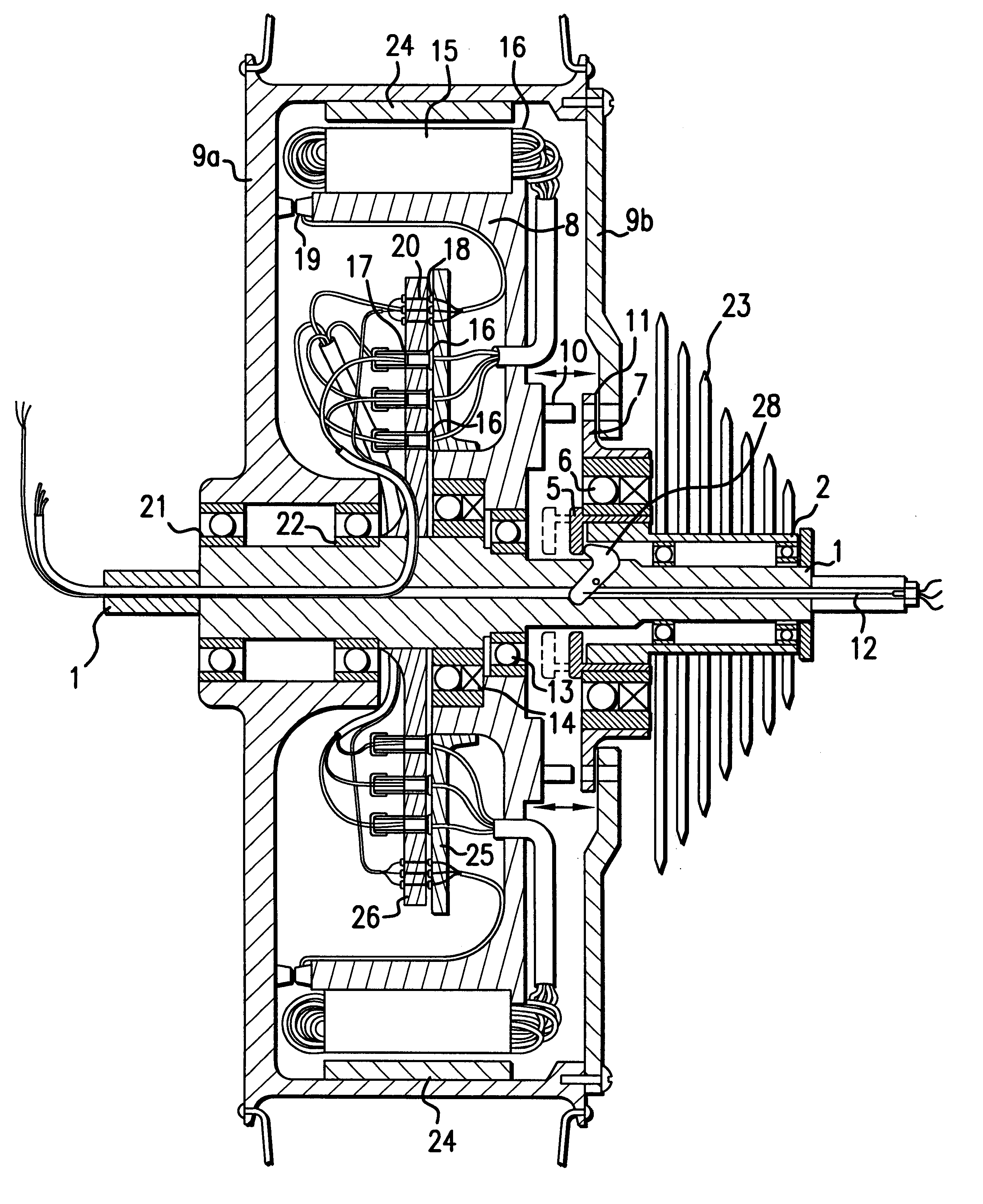
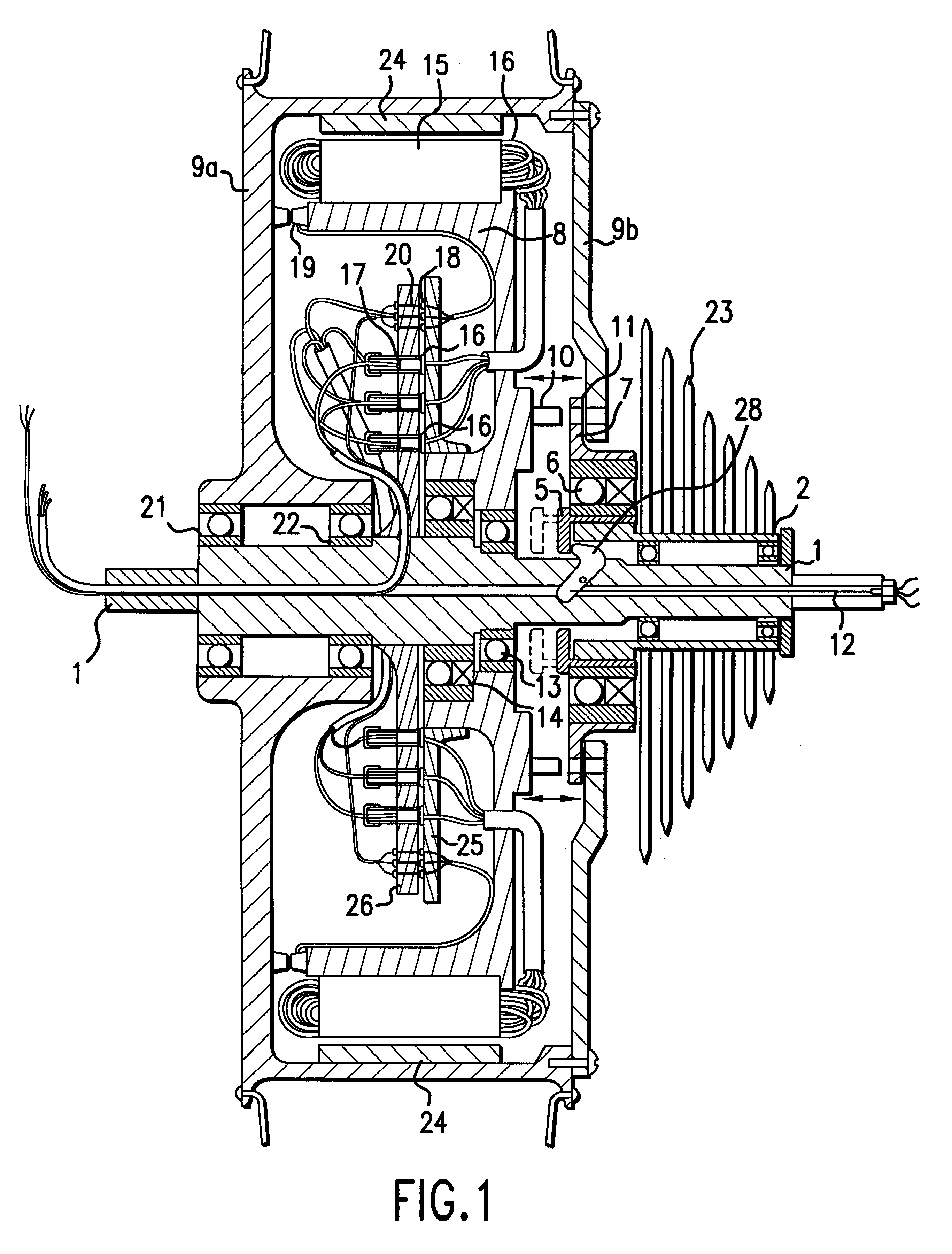
The exemplary embodiment shown in FIG. 1 is a possible arrangement of a propulsion system in accordance with this invention in a bicycle, using a brushless d.c. motor and a one-sided seating of a rotor designed as a wheel hub.

In the example represented, a rotor 9 of an electric motor, which is electrically driven with first rotations per minute (rpm) with respect to a stator 8, is designed as the hub of a wheel enclosing the stator. The stator 8 of the electric motor is rotatably seated and can be driven at second, arbitrary rpm by the toothed rings 23 of a pedal drive by means of the mechanism which will be subsequently described. Rpm resulting at the rotor 9, i.e. the hub of the wheel, corresponds to the sum of the first rpm and the second rpm.

A sleeve 2 is rotatably seated by means of ball bearings 3 and 4 on a central, hollow axle 1 and is frictionally connected with the toothed rings 23 of the pedal drive. A flange-like element 5 is pushed over one end of the sleeve 2 and is in...


PUM


Abstract

A hybrid drive mechanism for a wheel-driven vehicle. The drive mechanism has an electromotor with a rotor and a stator as a first drive source, with a first speed and a first torque, and a pedal drive as a second drive source, with a second speed and a second torque. The stator of the electromotor is positioned on an axle or shaft of the drive train between the pedal crank and the drive wheel, preferably on a wheel axis, in such a way that it can rotate. The stator can be coupled mechanically with the second drive source so that the stator is driven by the second drive source, and the rotor of the electromotor has a speed which corresponds to the sum of the first speed of the first drive and the second speed of the second drive.

Description

1. Field of the InventionThis invention relates to a hybrid propulsion system for a wheel-driven vehicle with an electric motor, which has two propulsion sources.2. Description of Prior ArtAuxiliary electrical propulsion systems for vehicles powered by a rider, such as bicycles, tricycles and wheelchairs, have been known for some time.Propulsion by an auxiliary electric motor is common to all these known vehicles, wherein the motor drives the driven wheel in parallel with the muscle power of the rider. This means that both sources of propulsion act in parallel to provide propulsion, so that their driving torque is added together.As a result, the two sources of propulsion, the electric motor and the muscle power, act on the same driven wheel. The rpm of the two sources of propulsion are therefore coupled.An increase in the rpm of the one source of propulsion does not necessarily result in a noticeable increase in the speed of movement. Instead, the other source of propulsion is relie...

Claims


Application Information

Patent Timeline
Patent Type & Authority Patents(United States)
IPC IPC(8): B62M7/12B62M23/02B62M7/00B62M6/40B62M6/65
CPCB62M6/40B62M7/12B62M6/65
Inventor KUTTER, MICHAEL
Owner KUTTER MICHAEL
Why Eureka
Try Eureka