
Deep drilling device

a drilling device and deep-drilling technology, which is applied in the direction of metal-working holders, positioning devices, support, etc., can solve the problems of large size, time-consuming and expensive, and the different positioning of the drilling hole with respect to the orientation and/or location, so as to increase achieve the effect of increasing the productivity of the deep-drilling devi

Inactive Publication Date: 2001-09-11
TBT TIEFBOHRTECHN
View PDF16 Cites 29 Cited by
  • Summary
  • Abstract
  • Description
  • Claims
  • Application Information

AI Technical Summary

Benefits of technology

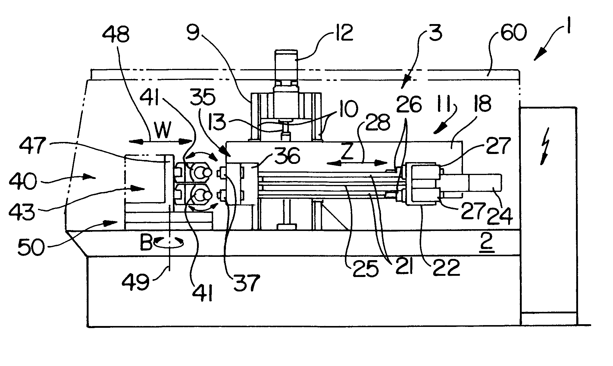
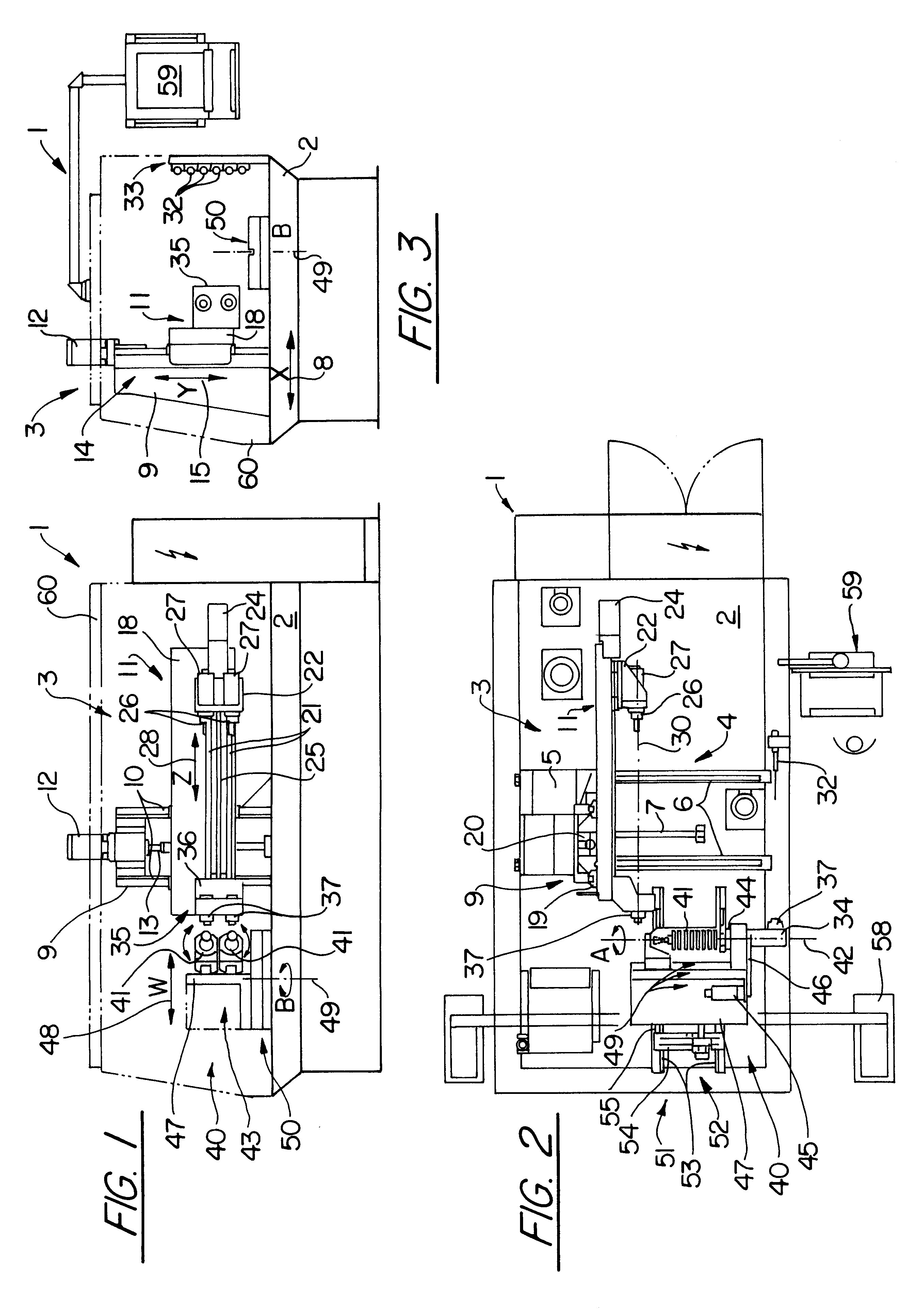
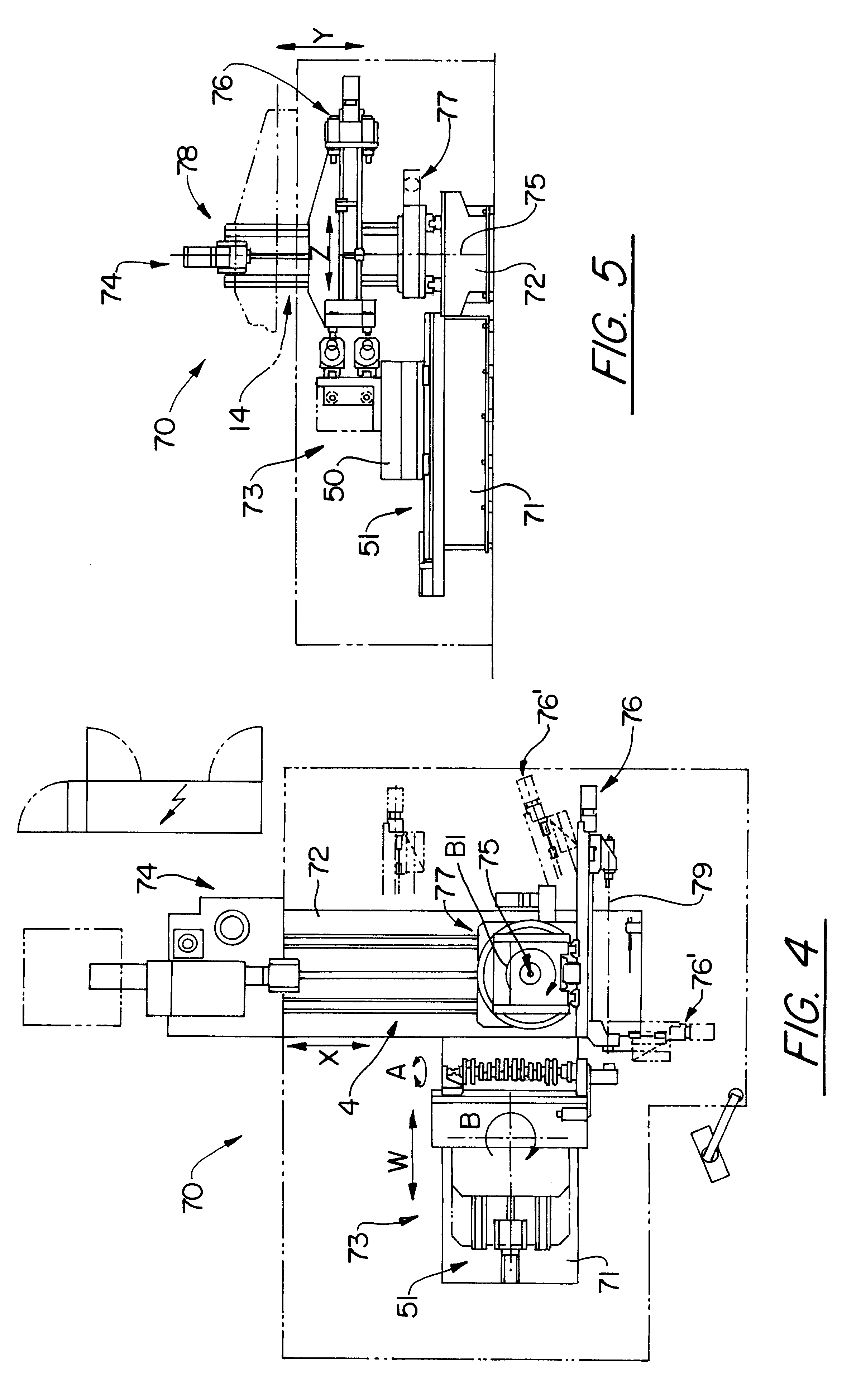
A work holding unit separate from the deep drilling unit has a first partial device for holding at least one workpiece with horizontally oriented workpiece longitudinal axis and for rotating the workpiece about said horizontal axis (A axis). A second partial device rotates the workpiece, particularly of the first partial device, about a vertical rotation axis (B axis). Thus, the workpiece holding unit has all the functions necessary for swivelling the workpiece and as a result of rotations about the A axis different circumferential portions of the workpiece can face the deep drilling tool and by rotations about the B axis it is possible to set different tilt angles of the holes relative to the workpiece longitudinal axis. Particularly in the case of installations for larger workpieces, to avoid excessively large axial movements it is also possible to make the tool-carrying parts of the deep drilling unit swivellable about a vertical axis (B2 axis).
Correspondingly an associated headstock can have several, particularly two superimposed, axially parallel main spindles or there can be several superimposed headstocks. A corresponding tool guidance device can have several, particularly two, four, six or eight, etc. axially parallel, superimposed tool guides. As a result of the appropriate superimposing of workpieces, drill bushings, tools and spindles with respect to multiple machining a productivity increase for the device is readily achievable, without it being necessary to modify horizontal structural dimensions compared with individual machining devices or without having to add to the existing construction area on the machine frame.

Problems solved by technology

A retooling of such transfer lines for the manufacture of workpieces, where the holes are differently positioned with respect to the orientation and / or location is complicated, time-consuming and expensive.
The design of this installation is complicated and it has a considerable size, whilst being complicated to handle.

Method used


Image

  • Deep drilling device
  • Deep drilling device
  • Deep drilling device

Examples


Embodiment Construction

The embodiment of an inventive deep drilling unit 1 shown in FIGS. 1 to 3 is based on a standard deep drilling centre, in which a deep drilling unit 3 is fixed to the top of a machine bed 2. The unit 3 has a first positioning device 4 with a cross-slide 5 slidably guided on two axially parallel linear guide rails 6 and by means of a not shown, first NC drive motor can be moved by means of a first spindle drive 7 parallel to a horizontal, first axis 8 (X axis).

On the cross-slide is located a column 9 with a pair of vertically oriented, axially parallel linear guide rails 10, on which is vertically movably guided a tool carrier device 11. For raising and lowering the tool carrier device 11 is provided a NC motor, e.g. a servomotor 12 placed on the top of the column and whose motor axis is parallel to the axes of the linear guides 10 and which acts by means of a vertical, second spindle drive 13 positioned between the guide rails 10 on the back of the tool carrier device 11. This provi...


PUM

PropertyMeasurementUnit
Angleaaaaaaaaaa
Centrifugal forceaaaaaaaaaa
Diameteraaaaaaaaaa

Abstract

A deep drilling device suitable for drilling in workpieces, particularly crankshafts, holes at different positions and / or in different orientations relative to a work longitudinal axis, has a deep drilling unit and a work holding unit cooperating therewith. The deep drilling unit permits parallel displacements of the deep drilling tools in a horizontal X direction and a vertical Y direction, as well as a tool feed parallel to the spindle axis. The tool holding device receives one or more crankshafts in such a way that their longitudinal axis is horizontally oriented and permits a rotation about the longitudinal axis and a swivelling of the workpieces about a vertical rotary axis. As a result both different tilt angles of the holes relative to the work longitudinal axis and also different positions of the holes relative to the circumference of the workpieces can be obtained.

Description

The invention relates to a deep drilling device for drilling holes in workpieces, particularly crankshafts, the holes being introduceable at different positions and / or in different orientations relative to a workpiece longitudinal axis.As is known, crankshafts for internal combustion engines for air or land vehicles, ships or stationary equipment are frequently provided with numerous holes, which are at different positions and / or in different orientations relative to the crankshaft longitudinal axis and which can e.g. serve as oil holes. During the mass manufacture of such workpieces frequently transfer lines with several work stations are used and in each work station are made in the workpiece one more holes having a specific orientation and positioning. A retooling of such transfer lines for the manufacture of workpieces, where the holes are differently positioned with respect to the orientation and / or location is complicated, time-consuming and expensive. Particularly for the pro...

Claims


Application Information

Patent Timeline
IPC IPC(8): B23Q1/60B23Q1/62B24B5/48B23B41/02B23B41/00B24B5/00B23Q1/25B23B41/12B23Q1/48
CPCB23B41/02B23Q1/60B23Q1/621B24B5/48Y10T29/5114Y10T483/16Y10T408/3809Y10T29/5107Y10T408/3811Y10T483/1736
Inventor RANDECKER, HERMANN
Owner TBT TIEFBOHRTECHN
Learn More