
System and method for driving organic EL devices

a technology of organic el and display, applied in the direction of instruments, static indicating devices, etc., can solve the problems of increasing the current i1 and affecting the quality of the display, and affecting the display quality

Inactive Publication Date: 2001-09-11
FUTABA CORPORATION
View PDF6 Cites 24 Cited by
  • Summary
  • Abstract
  • Description
  • Claims
  • Application Information

AI Technical Summary

Benefits of technology

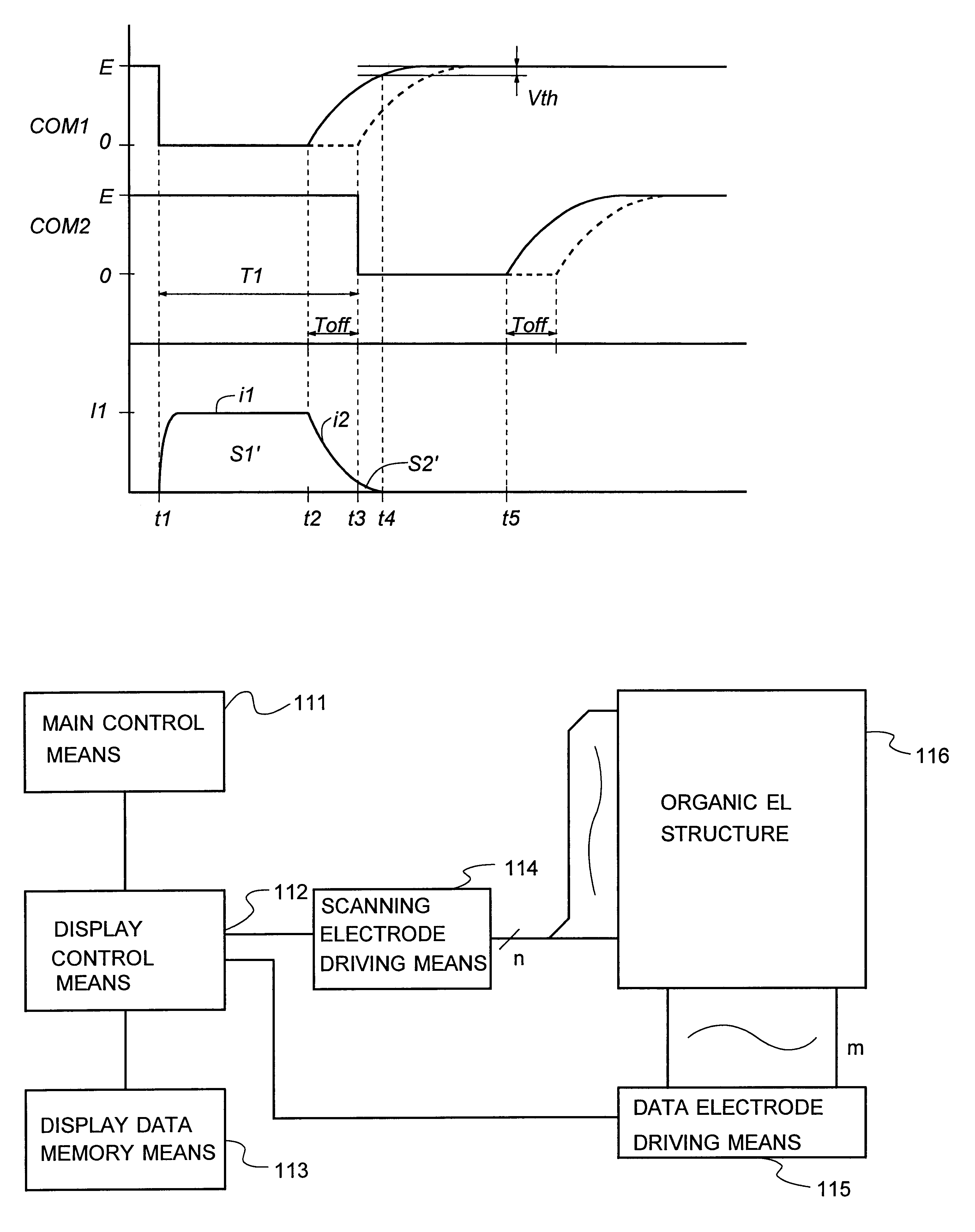
According to the present invention as explained above, it is possible to achieve an organic EL display driving system and method that enables an organic EL display to be driven with neither a contrast lowering nor a false light emission phenomenon yet in simple construction.

Problems solved by technology

Such false light emission makes contrast worse or is perceived as anomalous light emission, resulting in considerable drops of the quality of the display or a disturbance factor in images.
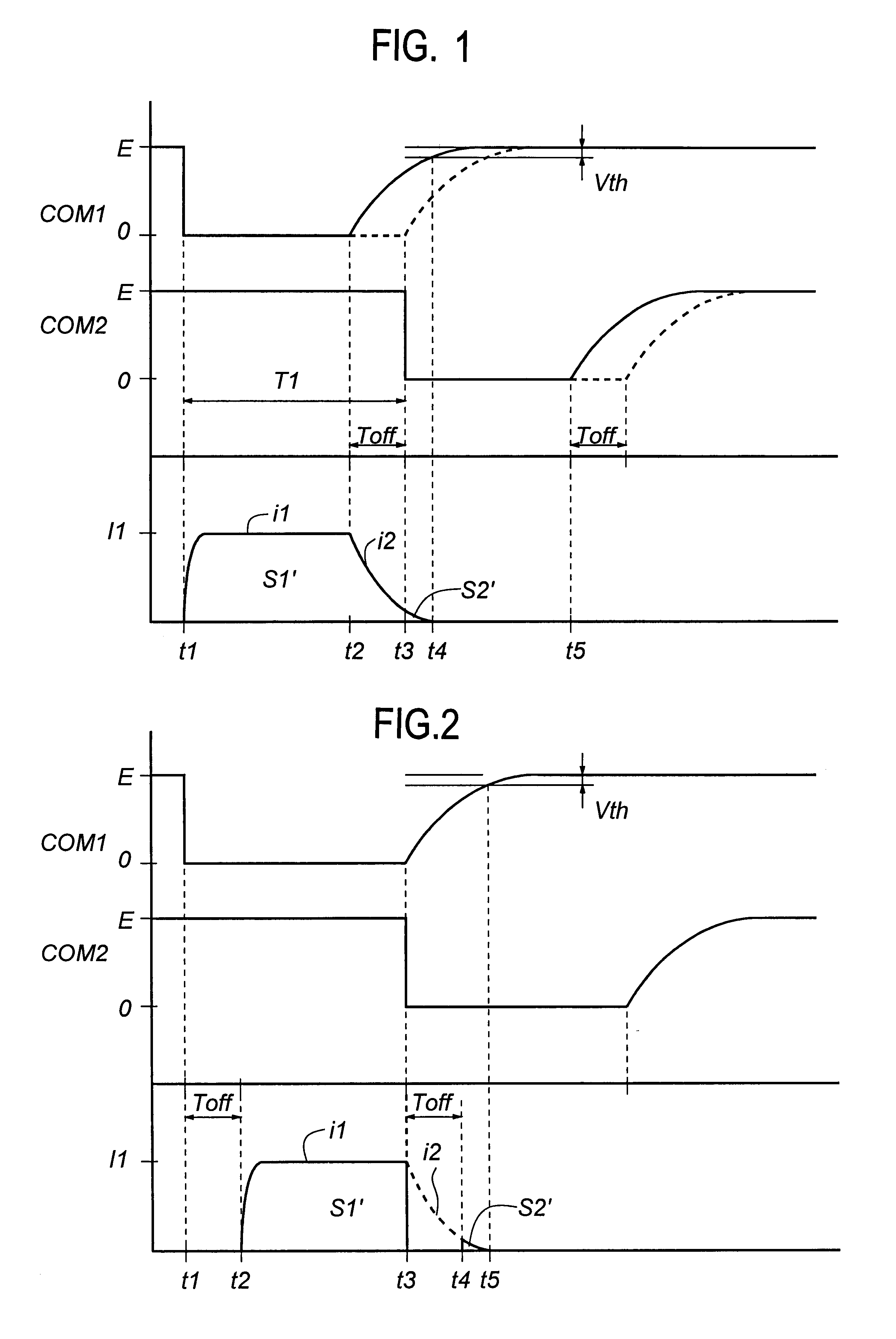
For this reason, overlapping light emission occurs between a certain driving line and the next driving line, resulting in a contrast lowering and an anomalous light emission phenomenon.
Even when the data electrodes are driven at a constant current or voltage, on the other hand, the rise of the current i1 becomes dull if the parasitic capacity of the device is large.
However, such as when the combined capacity C increases with increases in the device area and the number of devices on one scanning line and the resistance components R such as the pull-up resistance of the scanning electrode and the on-resistance of the switching element in the push-pull circuit cannot be reduced, it is impossible to satisfy the condition (4), resulting in a contrast lowering and drops of viewability and image quality.

Method used


Image

  • System and method for driving organic EL devices
  • System and method for driving organic EL devices
  • System and method for driving organic EL devices

Examples


example 1

FIG. 4 is a circuit diagram illustrative of the first example of the control means according to the present invention. In this example, a commercially available thermal head driver is used. By use of such a commercial IC, it is possible to save the expense needed for the development and fabrication of ICs and slim down the fabrication cost of the system.

In FIG. 4, data applied to an output stage 121 for driving the organic EL structure are captured from a serial input terminal SI by way of a buffer 125, and serially integrated into each flip-flop 129 in the right direction of the paper in response to a clock signal applied to a clock terminal CLK. It is here noted that this input signal can be fetched from a serial output terminal SO by way of a buffer 125.

The signal captured in each flip-flop 129, if required, may be latched in the flip-flop 128 by a latch signal entered from a latch input terminal LT and applied by way of a buffer 124. In this example, however, this function is no...

example 2

FIG. 6 is a circuit diagram illustrative of the second example of the control means according to the present invention. In this example, a commercially available PDP driver is used. By use of such a commercial IC, it is again possible to save the expense needed for the development and fabrication of ICs and slim down the fabrication cost of the system.

In FIG. 6, data for driving the organic EL structure (data electrode driving signal) are captured in a shift register 145 by way of a serial input terminal A or B. Then, the data appear serially at output terminals in the form of output signals S1 to Sn in synchronism with clocks in response to clock signals applied from a clock terminal CLK by way of a Schmitt inverter 144. It is noted that this shift register 145 enables the direction of shift to be set in response to a signal entered in a direction control terminal R / L.

The output signals S1 to Sn of the shift register 145 are entered in a latch 146 to slue or keep them at terminals ...


PUM


Abstract

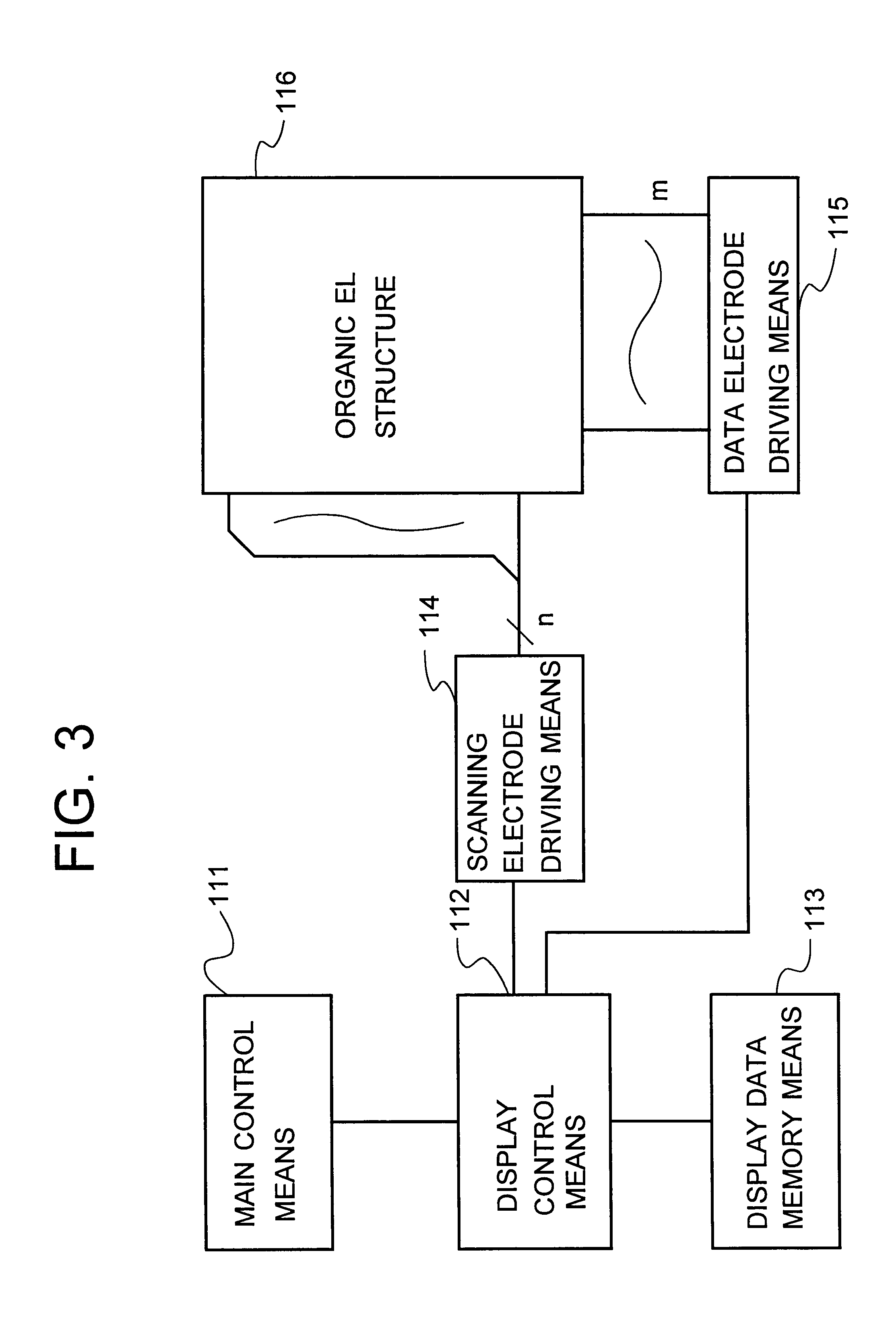
The invention has for its object to provide an organic EL display driving system and method enabling an organic EL display to be driven with neither a contrast lowering nor a false light emission phenomenon yet in simple construction. The driving system and method drive an organic EL device which comprises at least one set of scanning electrodes and data electrodes arranged in a matrix fashion and an organic material-containing organic layer located between said scanning and data electrodes and taking part in at least a light emission function, with one closed circuit formed through at least one set of electrodes. When the scanning and data electrodes are driven, a given non-selection time is provided between driving one electrode and driving the next electrode.

Description

TECHNICAL ARTThe present invention relates to a system and method for driving an organic EL display which is constructed using an organic compound and has applications in the fields of information display panels used on audio equipment, automotive measuring instrument panels, displays for displaying moving images and freeze-frame pictures, household electrical appliances, car and bicycle electrical equipment, etc.In recent years, an organic EL device has been intensively studied and put to practical use. The organic EL device is basically built up of a tin-doped indium oxide (ITO) or other transparent electrode, a triphenyldiamine (TPD) or other hole transporting layer laminated on the transparent electrode, an organic light emitting layer formed of a fluorescent material such as an aluminum quinolinol complex (Alq.sup.3) and laminated thereon, and a metal electrode (electron injecting electrode) provided on the organic light emitting layer and formed of a material having a low work...

Claims


Application Information

Patent Timeline
Patent Type & Authority Patents(United States)
IPC IPC(8): G09G3/32
CPCG09G3/3216G09G3/3266G09G3/3291G09G2320/066G09G2320/0223G09G2320/0606G09G2310/065G09G3/30
Inventor SUZUKI, MITSUNARISAITOH, YOSHIHIROKAITA, YOSHIOFURUKAWA, HIROTADA
Owner FUTABA CORPORATION
Learn More