Method and apparatus for implementing a high-precision interval timer utilizing multiple oscillators including a non-optimal oscillator

a technology of high-precision interval timer and reference oscillator, which is applied in the field of oscillators, can solve the problems of significant power consumption of these oscillators, increased cost of manufacturing 32 khz oscillators, and khz oscillators

Inactive Publication Date: 2001-09-18
QUALCOMM INC
View PDF0 Cites 29 Cited by
  • Summary
  • Abstract
  • Description
  • Claims
  • Application Information

AI Technical Summary

Problems solved by technology

One major disadvantage of utilizing a 32 kHz oscillator is the increased cost associated with the manufacture of 32 kHz oscillators when compared to the extremely high-volume manufacturing of 32.768 kHz oscillators.
One significant disadvantage associated with using high-speed oscillators is the significant power consumed by these oscillators.
One technique for constructing Bluetooth protocol device timers that overcomes the disadvantages associated with the techniques described above (i.e., the increased cost and power consumption), makes use of non-optimal low-speed oscillators, "swallow" counters, and divide-by counters.
One disadvantage of using non-optimal oscillators in a timer is the "jitter" that is inherently introduced by the process of swallowing clock pulses.
Disadvantageously, the swallow counters used in these designs inherently produce "jitter" due to the non-optimal nature of the oscillators.
Thus, for every pulse counted by the swallow counter used in the above-described method, a time error linearly increases until a pulse is deleted.
The error of up to 30.5176 .mu.sec can adversely affect the performance of certain functions of wireless devices, including Bluetooth devices.
Such a method should consume relatively small levels of power.
The use of a low-speed non-optimal oscillator decreases the overall power consumption of the wireless device.

Method used


Image

  • Method and apparatus for implementing a high-precision interval timer utilizing multiple oscillators including a non-optimal oscillator
  • Method and apparatus for implementing a high-precision interval timer utilizing multiple oscillators including a non-optimal oscillator
  • Method and apparatus for implementing a high-precision interval timer utilizing multiple oscillators including a non-optimal oscillator

Examples


Embodiment Construction

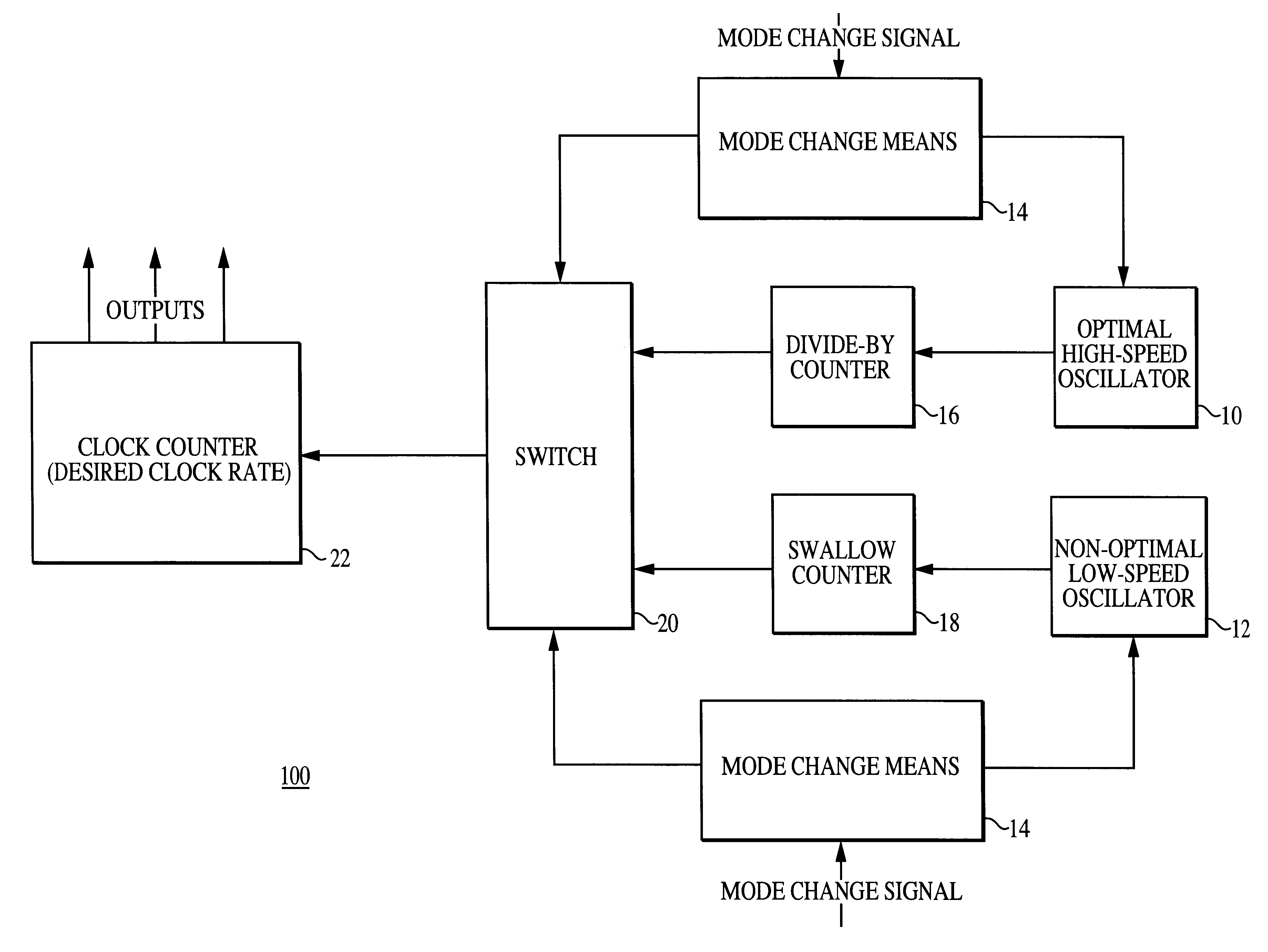
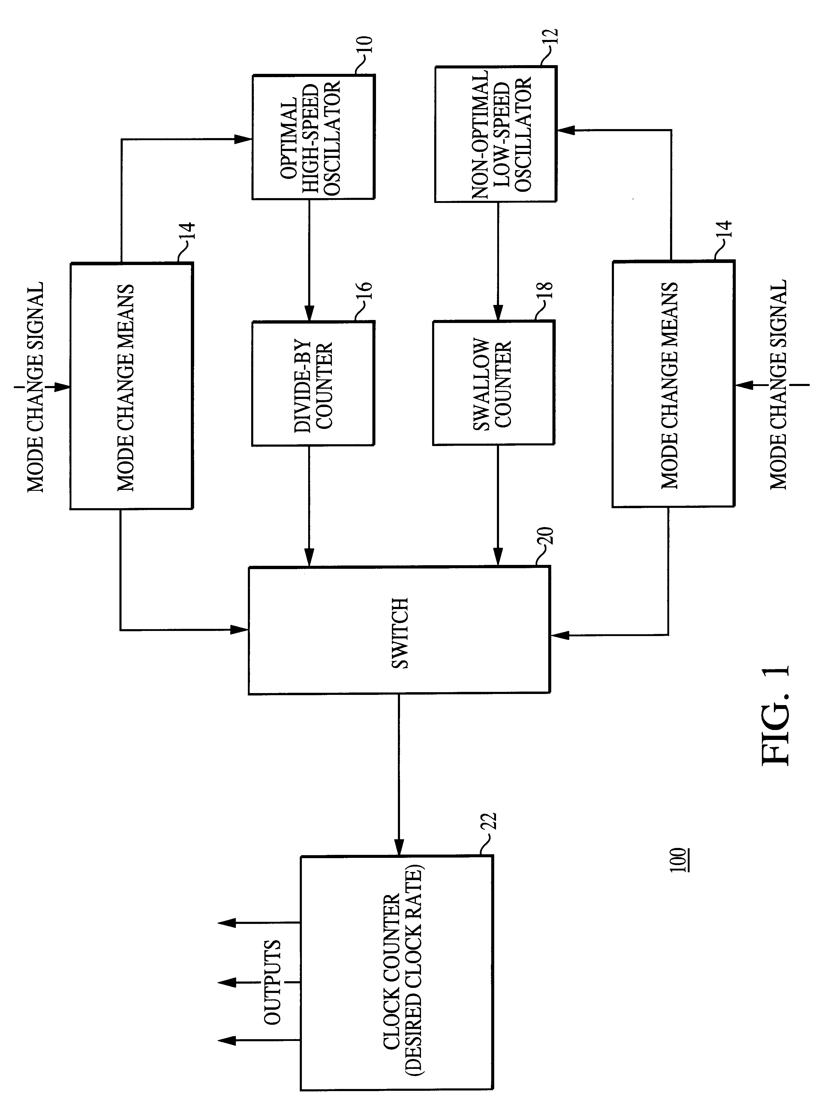
The present inventive method and apparatus preferably includes a counter and at least two oscillators. The preferred embodiment of the present invention includes a high-speed optimal oscillator and a low-speed non-optimal oscillator. The counter is preferably clocked by the high-speed optimal oscillator during on-the-air modes of operation, and by the low-speed non-optimal oscillator during sleep modes of operation.

FIG. 1 shows a block diagram of the preferred embodiment of a timer 100 of the present invention using two oscillators. An optimal high-speed oscillator 10 outputs a first clock rate signal. The first clock rate signal is input to a divide-by counter 16 as shown in FIG. 1. The divide-by counter 16 outputs a first clock signal at a desired clock rate to a first input of a switch 20. Similarly, a non-optimal low-speed oscillator 12 outputs a second clock signal (operating at a second clock rate). The second clock signal is input to a swallow counter 18. The swallow counter ...


PUM


Abstract

The present invention is a novel method and apparatus for implementing a high-precision timer utilizing a non-optimal oscillator and a high-speed oscillator wherein only one oscillator is enabled at a given moment in time. The high-precision timer method and apparatus comprises a timer and an error-correction technique. In one embodiment, the timer of the present invention is constructed from a high-speed oscillator and a low-speed non-optimal oscillator. The timer operates from the high-speed oscillator during on-the-air modes of operation and from the low-speed non-optimal oscillator during sleep modes of operation. The present inventive method corrects errors that are introduced by the non-optimal oscillator and a swallow counter. The errors are corrected using an error-correction technique having two steps: an error-determination step and an error-correction step. In the preferred embodiment of the error-determination step, a total error for a time interval is determined by performing the following steps: (1) calculating an individual error that occurs at each pulse; (2) multiplying the individual error by the number of pulses occurring during the time interval; and (3) adjusting for a non-optimal counter. Once an error has been determined, the error-correction step adjusts a clock counter accordingly. Depending upon the error-correction technique used, the error-correction step can correct the total error at one of several locations within a timer counter chain that is used to practice the present invention. The implementation of the present invention allows a straightforward realization of multiple timers.

Description

1. Field of the InventionThis invention relates to oscillators for use in wireless devices, and more particularly to a method and apparatus for implementing a high-precision interval timer utilizing multiple reference oscillators including a non-optimal oscillator.2. Description of Related ArtTimers, clocks and oscillators are essential to the performance of most modern electronic devices. Examples of devices that use clocks, oscillators and timers are commonplace. For example, digital timepieces (e.g., digital wristwatches), computers, videocassette recorders (VCRs), televisions, cordless telephones and wireless communication devices (e.g., cellular phones, pagers and Internet-enabled personal digital assistants (PDAs)) all have timers that generate internal clock signals that are used by the devices. Timers or clocks produce a desired clock rate by counting for a desired time interval. Examples of such time intervals include 1 second (i.e., operating at a 1 Hz clock rate) and 1 mi...

Claims


Application Information

Patent Timeline
Patent Type & Authority Patents(United States)
IPC IPC(8): G06F1/08G06F1/14G04G3/00G04G3/02G04F1/00H03L7/00
CPCG04F1/005G04G3/02H03L7/00G06F1/14G06F1/08
Inventor BOURK, TERRANCE R.RIEDEL, NEAL K.
Owner QUALCOMM INC
Why Eureka
Try Eureka