Furthermore, it has been shown to be advantageous to couple the rotor to the
flywheel by means of the
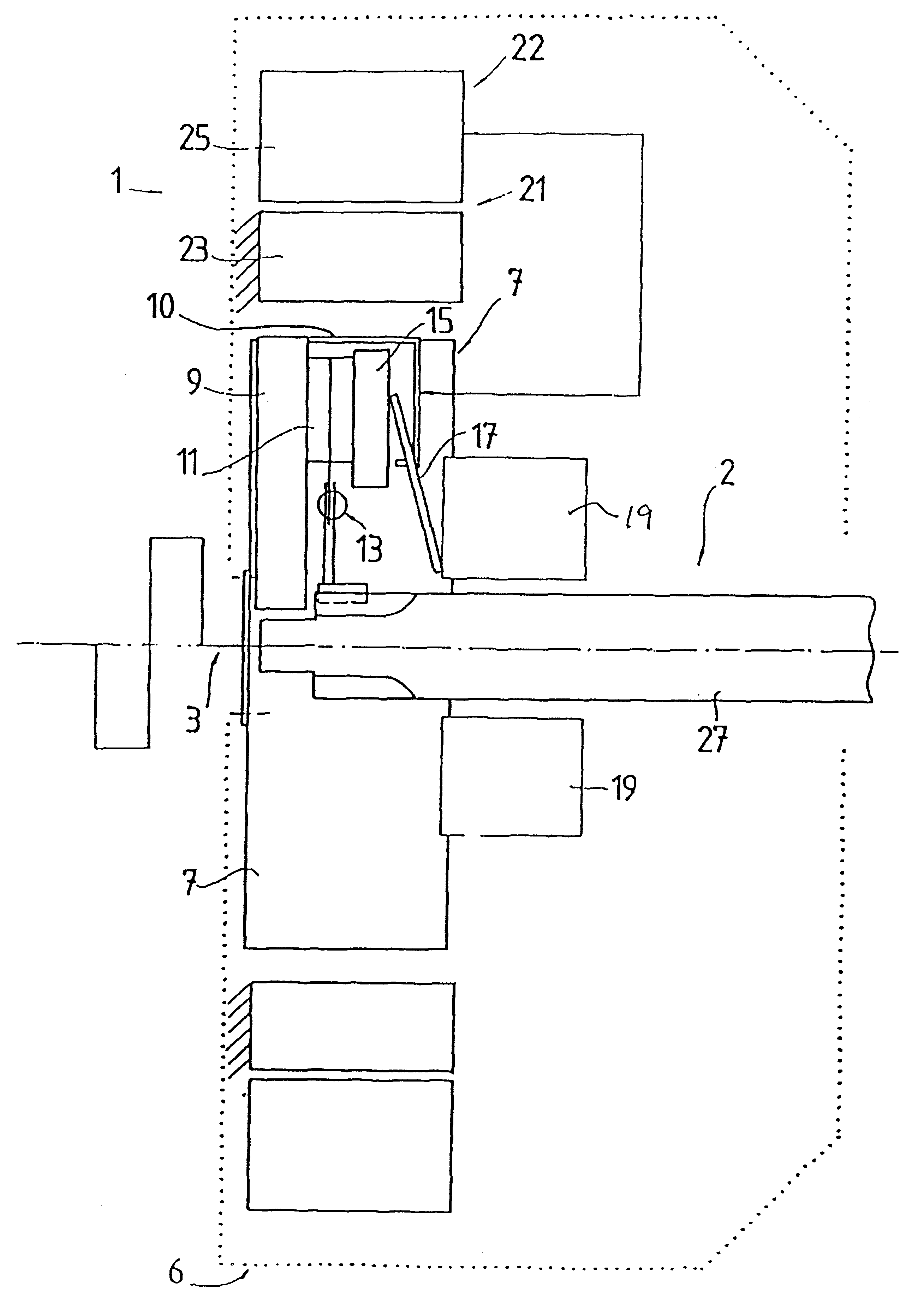
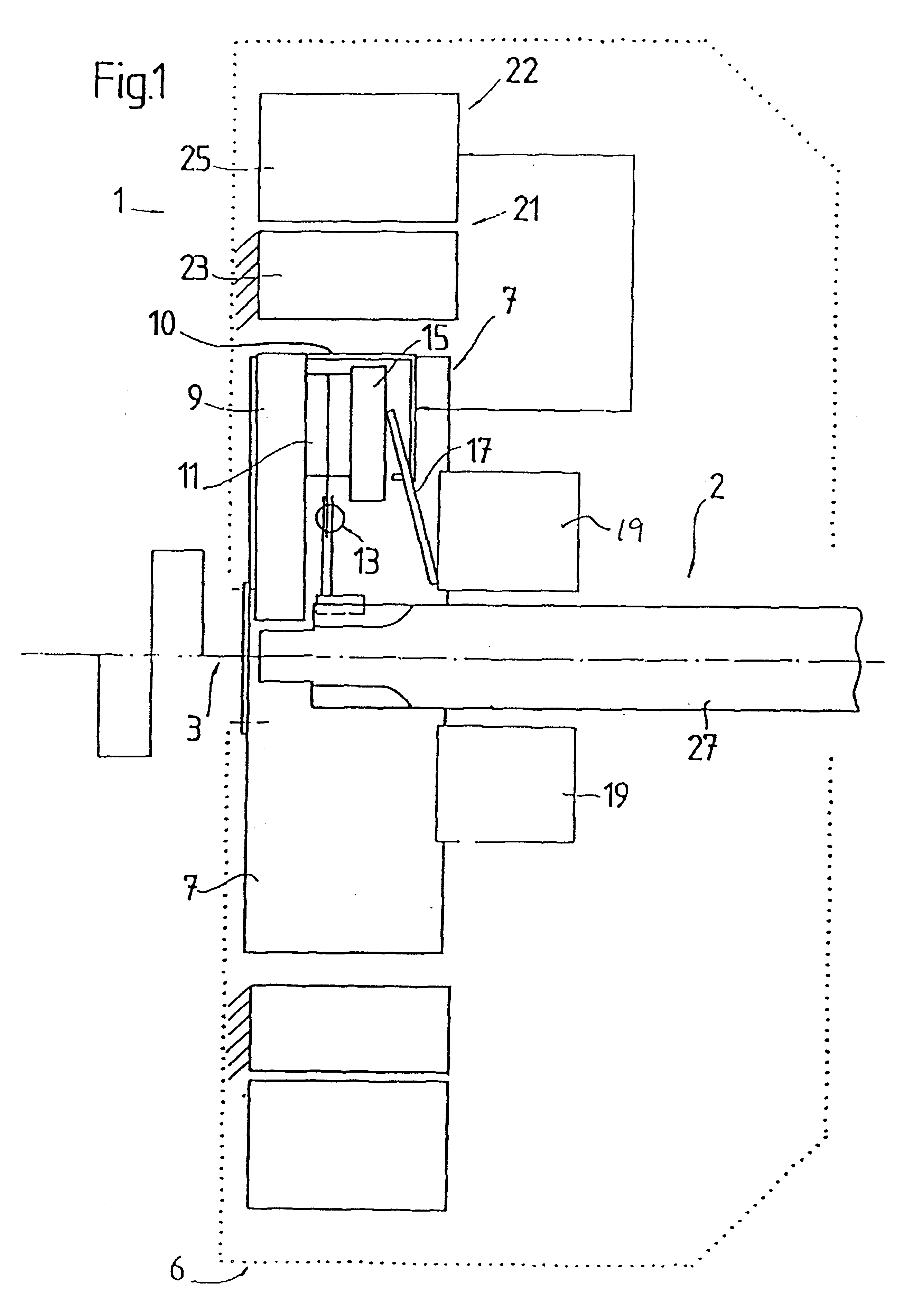
interlocking device. The rotor is preferably arranged coaxially with the
flywheel assigned to the internal combustion engine. In order to provide a high
moment of inertia, it is advantageous to provide an external rotor type as the electric
machine which, because of the large
radius, has a high
moment of inertia. It is also preferable for a compact clutch to be arranged radially inside the electric
machine as the clutch. It is also possible for other clutches, such as multi-plate clutches or wear-adjusting clutches to be provided. This drive arrangement is particularly compact and is especially suitable for use in passenger motor vehicles, in which the installation space is particularly tight. For use in utility motor vehicles, it may be advantageous to use a friction clutch having a large
diameter, via which a
high torque can be transmitted. There is generally more installation space available in utility motor vehicles, so that a
parallel arrangement of electric machine and clutch is possible.
In another embodiment, a
torsional vibration damper is interposed so as to couple the rotor to the drive
train. This torsional
vibration damper may comprise, for example, a spring element or else resilient dampers and associated stops. It has been shown to be advantageous to provide an adjustment mechanism for adjusting the position of rotor relative to the component to which the rotor can be coupled. By means of adjusting the relative position of rotor and the associated component of the drive train, the effectiveness and the working point of the torsional
vibration damper is adjustable. As a result, when the rotor is coupled, the torsional vibration damping can be matched to the expected vibrations.
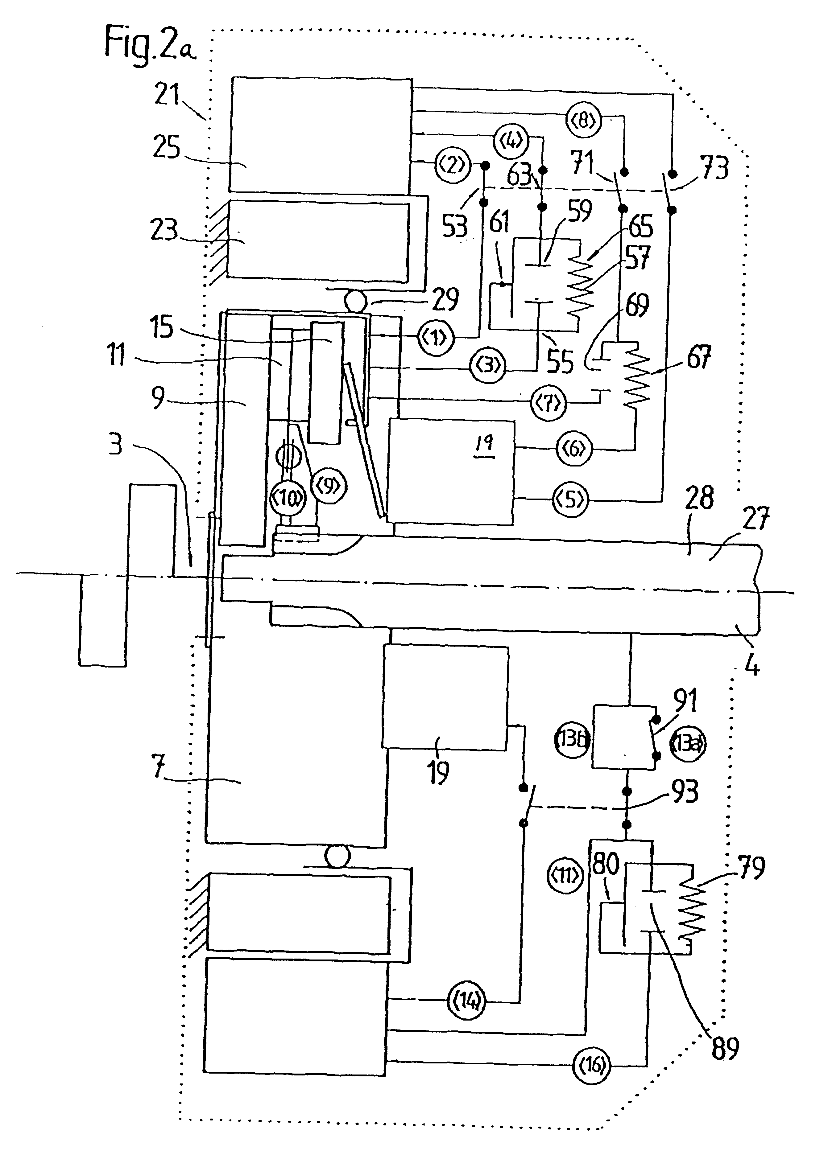
In a further embodiment, provision is made for the clutch to be provided with a rotationally operated clutch operator, which can be operatively connected to the electric machine. In order to disengage the clutch, the necessary rotational movement can be introduced by activating the electric machine. It is therefore possible for the electric machine to be used for active and passive vibration damping (particularly in operating situations in which severe vibration is to be expected), and to be provided for operating the clutch. The torque introduced by the internal combustion engine is preferably reduced before the clutch is disengaged. This is also associated with a reduction in the torque fluctuations, so that it is possible to dispense with any damping of the torque fluctuations by means of the electric machine.
In a further embodiment, provision is made for the rotor to be able to be coupled to the output drive shaft by means of an
interlocking device. As a result, the output drive shaft, which is preferably at the same time the gearbox input shaft, can be accelerated by activating the electric machine. The possibility of accelerating or retarding the output drive shaft by means of the electric machine is particularly advantageous for the purpose of active synchronization during a shifting operation.
In yet a further embodiment, a selector device is provided whose selector position enables the rotor to be selectively coupled to the clutch operator or to the output drive shaft. If the rotor is connected to the clutch operator by the selector device, then the clutch can be operated by activating the electric machine. If, on the other hand, the rotor is coupled to the output drive shaft via the selector device, active synchronization and vibration damping can be provided by the electric machine. In a further embodiment, provision is made for the
stator to be mounted by means of a bearing so that it can rotate with respect to a component fixed to the bodywork. The stator is assigned a locking device by means of which any relative rotation can be prevented. Because of the force acting to conserve
momentum, when the locking device is released, the stator is accelerated in a direction opposite to the rotational movement of the rotor. As a result of this deflection of the stator, the movement of the rotor is uniformly dampened.
It is advantageous to couple the stator to the rotationally operated clutch operator so that the rotational movement needed for operating the clutch can be introduced by the electric machine as a result of the activation of the electric machine, and on account of the
restoring force which acts when the locking device is released. It is preferable if, by renewed switching of the locking device, the clutch can be locked, even in the disengaged state, or the stator can be locked in the appropriate position. In order to engage the clutch, it is advantageous to firstly reintroduce the
restoring force provided to disengage the clutch and, in this state, to release the locking device in order to then reduce the
restoring force which acts in order to engage the clutch.

