
Snap-fitting, non-dislocating hip joint socket implant

a hip joint socket, non-dislocation technology, applied in the field of single-piece, monolithic plastic enarthrodial type joint socket implants, can solve the problems of reduced overall depth of the prosthetic head-contraint socket, unable to ensure a maximally efficient unable to ensure maximum implant-stabilizing bone-to-prosthesis cement mantle, etc., to prolong the life of the a

Inactive Publication Date: 2001-10-09
BIOPRO
View PDF12 Cites 26 Cited by
  • Summary
  • Abstract
  • Description
  • Claims
  • Application Information

AI Technical Summary

Benefits of technology

In general summary, the present invention provides an improved enarthrodial type joint socket implant, useful in arthroplasty. In a particular embodiment, illustrative of the invention with a complement of beneficial features, it pertains to certain specific modifications in the design configuration of former and current other polyethylene acetabular hip components, for example, for total conventional hip replacement, which not only enhance the proficiency and longevity of the stabilizing bone-prosthetic cement mantle in the interest of extending the survivorship longevity of the acetabular component, relative to the time to failure of the arthroplasty procedure, but also provide a secure snap-fitted articulation that produces the desired effect of guarding against the propensity for postoperative dislocation while at the same time allowing for a normal functional range of motion of multi-planed joint motion.
A second general part of the invention, particularly pertinent especially to conventional hip replacement acetabular cup prostheses, can concern an innovative snap-fitted arrangement of the head-restraining marginal outlet of the acetabular component. One feature of this second general part of the invention pertains to posterior and anterior "cut outs" of the implant to particularly avoid premature impingement against the prosthetic femoral neck, thus allowing a normal, non-dislocating range of unobstructed external and internal rotation of the hip. Although, if left uncompromised, a reduction in the marginal extension of the implant rim in these areas would ordinarily provoke a propensity for dislocation, this has been effectively addressed by a second feature of this second general part of the invention. This second feature pertains to a marginally extended continuation of the superior one-half or so of the cup containment that is of a sufficient magnitude to reduce the overall dimension of the socket outlet to less than a hemisphere, which, as a consequence, reconstitutes the desired advantages of a snap-fitted articulation without incurring the aforementioned listed disadvantages associated with other attempts to provide a snap-fitted arrangement by the means of a complete, uninterrupted circumferential extension of the marginal head constraint.
Advantages of the aforementioned first general part of the present invention include the following: 1) the design-related improvement in the physical mode of cement fixation and the technical ease of providing an appropriate, evenly distributed and universally thick cement mantle should ameliorate, or at the least, decelerate, the process of implant loosening complications and prolong the time to failure of the acetabular component; 2) a commensurately thicker polyethylene component can be accommodated by eliminating the space-occupying thickness of a metal-backed container; and 3) a reduction in the rate of polyethylene wear and the associated incidence and severity of debris-induced periprosthetic osteolysis, a commonly cited cause of premature implant loosening and related complications. Also, 4) an ability to effectively employ a socket implant made solely of ultra high molecular weight polyethylene (UHMWPE), which, when cemented as the present invention can provide and eliminating metal-to-bone contact, may reduce the rate or incidence of implant loosening due to the substitution of the metal with the more resilient implant and cement, and consequent lessening of bone resorption at the implant-bone interface. In addition, 5) avoiding the use of expensive metal-backed part in the component substantially reduces the overall cost of the replacement procedure.
Advantages of the aforementioned second general part of the invention arise from the beneficial effect associated with the appropriately positioned marginal cut-outs and in addition the superior extension of the socket outlet in the prevention of dislocation. Aside from the provision for a snap-fitted socket arrangement, the superiorly oriented rim extension produces an appropriately localized and extended "hood" that, in an by itself, provides an effective mechanical block against either antero-posterior or postero-superior dislocation, which are the commonly encountered directional modes of this complication. Concurrently, the strategically positioned posterior and anterior cut-out indentations augment the avoidance of dislocation by allowing a normal range of anterior and posterior hip rotations.

Problems solved by technology

In the meantime, the reduction in the spherical marginal extension of the implant to less than a hemisphere is, of course, accompanied by a commensurate reduction in the overall depth of the prosthetic head-constraining socket, and, consequently, the replaced hips remained vulnerable to the propensity for postoperative dislocation.
First, the nature and distribution of the shallow irregularities on the cemented outer surface of the polyethylene component makes it technically difficult, if not impossible, to assure a maximally efficient implant-stabilizing, bone-to-prosthesis cement mantle, i.e., a cement mantle that is symmetrically distributed to provide a consistently even and adequate thickness of cement throughout the total dimension of the bone-prosthesis interfacing interval.
Second, acetabular components which are designed with a femoral head-constraining marginal outlet that is reduced to less than a hemisphere are prone to postoperative dislocation. Although a relatively infrequent occurrence, postoperative dislocation of a replaced hip is an inordinately serious and disheartening complication. Aside from the severe discomfiting and emotional effect of the ordeal on the patient and surgeon alike, this complication has a substantial adverse impact due to the not insignificant costs associated with the required added surgical intervention and hospital care.
Third, polyethylene acetabular components that were designed with a complete circumferentially extended snap-in marginal outlet produced yet an earlier premature stage of marginal abutment against the neck of the femoral component, and an associated, commensurate reduction in the range of rotational motions, which in turn induce the propensity for a "leveraged-out" anterior or posterior joint dislocation, notwithstanding the snap-fitted arrangement. Furthermore, repetitive, motion-induced abutment between the femoral neck and the extended acetabular margin, particularly with rotary joint motions, resulted in erosive degradation of the repetitively traumatized, overextended margins of the acetabular cup outlet, consequentially producing yet another source for the proliferation and the associated detrimental effects of foreign body debris.
Fourth, cemented metal-backed acetabular components have had no demonstrable salutary effect on the incidence of implant loosening complications.
Fifth, long-term experience with the use of uncemented porecoated metal-backed components, although shown to be effective in stabilizing the implant, has demonstrated a substantive acceleration in the rate of polyethylene wear, and an associated significant increase in the incidence and severity of debris-induced periprosthetic osteolysis, occasionally with catastrophic consequences to the patient.
For instance, an inadvertent, erroneously suspected propensity for anterior dislocation that is managed by a precautionary antero-superiorly positioned rim extension may result in a marginally unguarded posterior dislocation, or vice versa.

Method used


Image

  • Snap-fitting, non-dislocating hip joint socket implant
  • Snap-fitting, non-dislocating hip joint socket implant
  • Snap-fitting, non-dislocating hip joint socket implant

Examples


Embodiment Construction

The invention can be further understood by the present detail which may be read in view of the drawings. The same is to be taken in in an illustrative and not necessarily limiting sense.

Although the joint of interest may be another enarthrodial joint, the invention is described primarily with respect to and preferably is the hip. For example, the joint of concern may be the human hip joint.

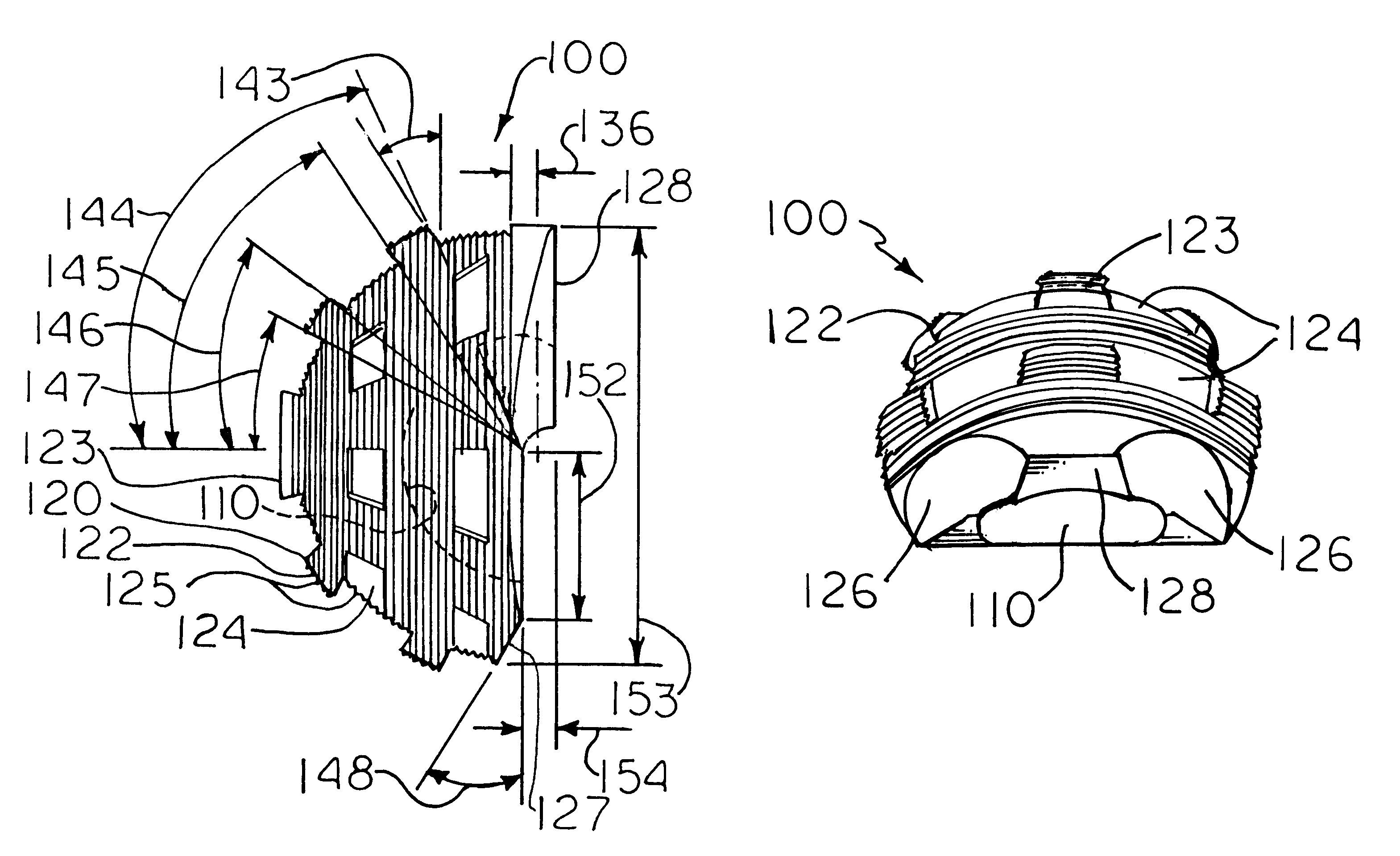
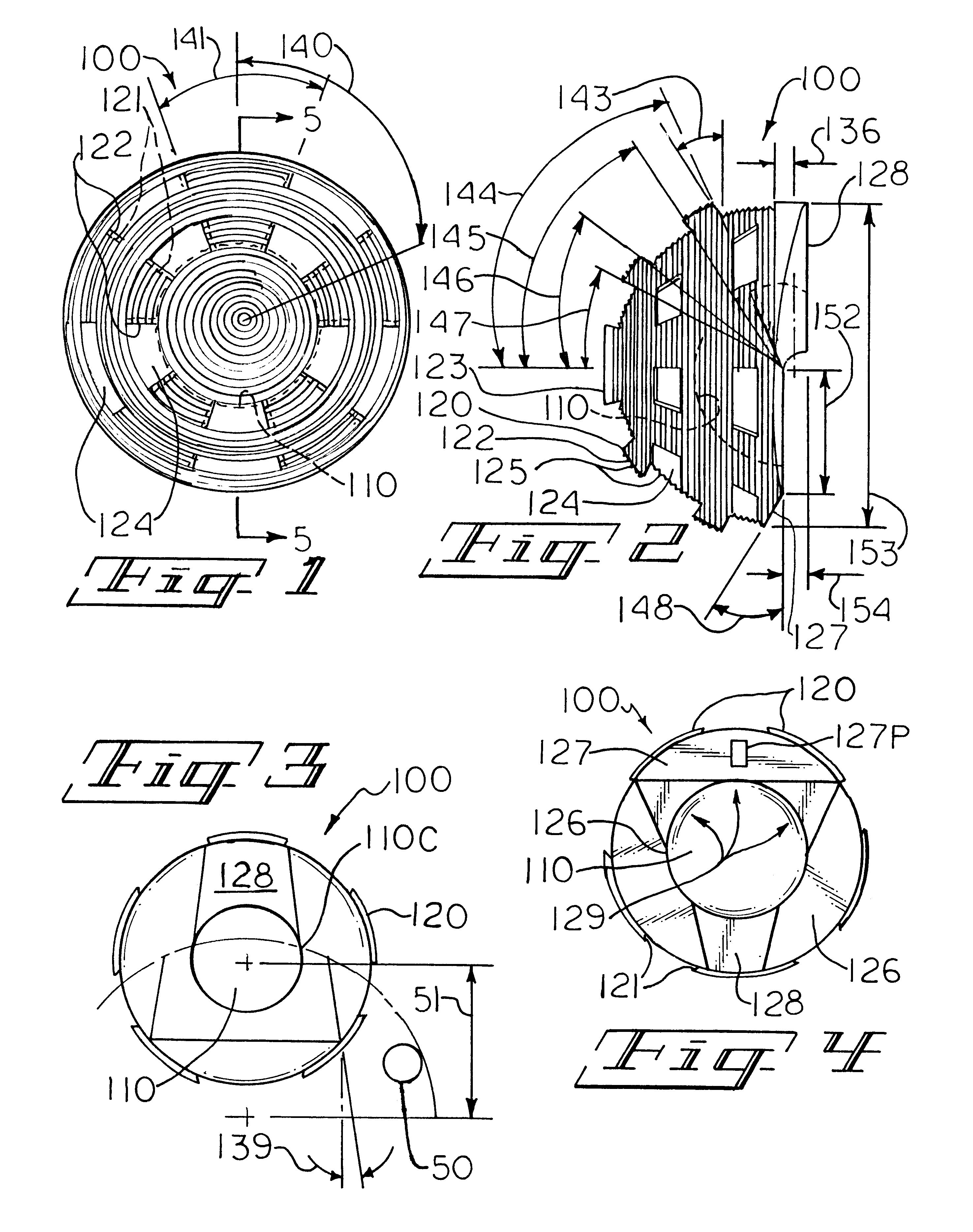
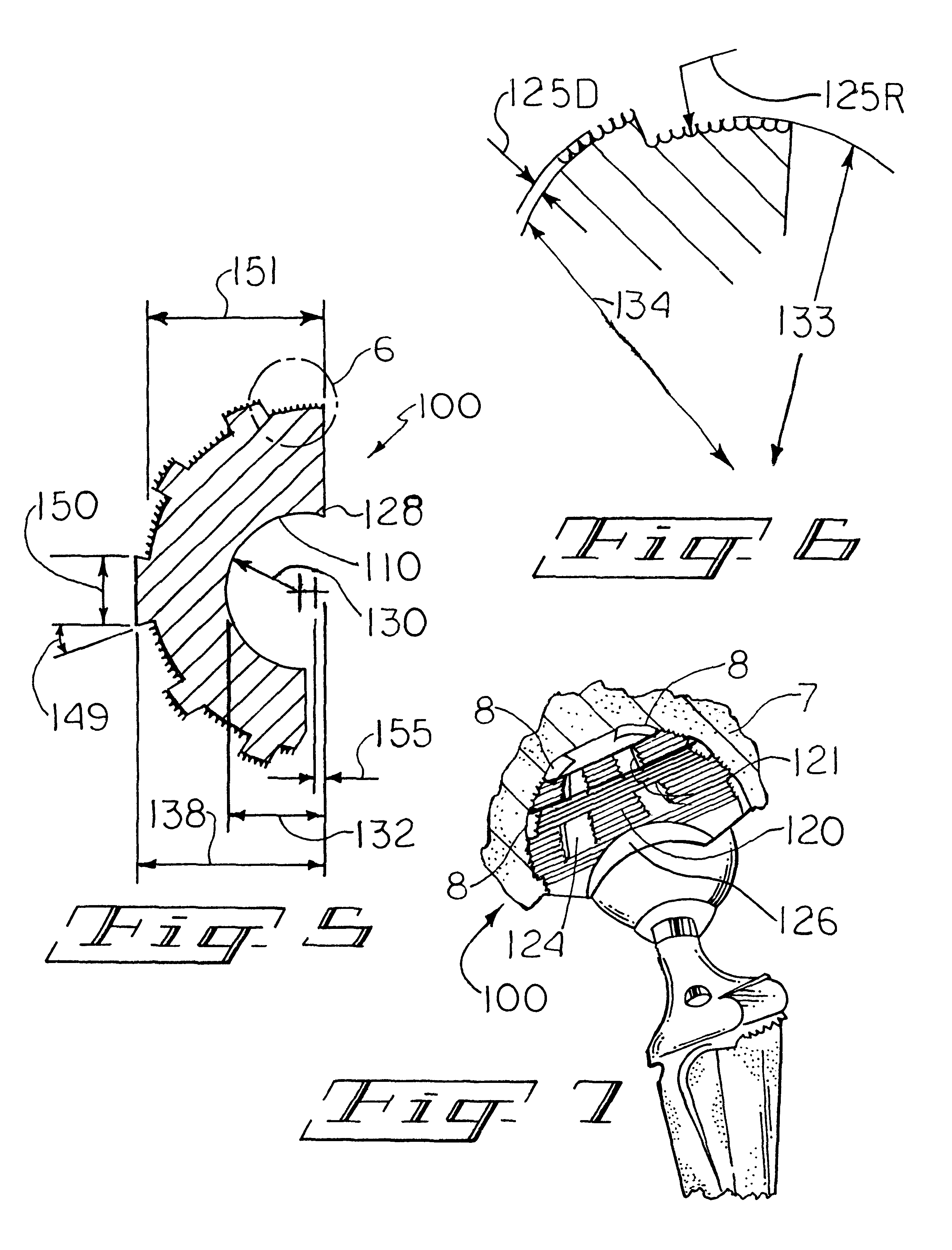
With reference to the drawings, features generally common to socket implants of the invention 100 (FIGS. 1-9) for a total conventional hip replacement, which may be referred to as a head-receiving socket implant cup 100 include supporting body 101, and articular surface 110 which is smooth, and a cementable, mountable back surface 120. The articular surface 110, when the cup 100 is suitably mounted in suitable receiving stock such as human cotyloid cavity bone 7 such as by cementing with a methacrylate surgical cement 8, mates in articulating, gliding contact with the smooth external surface the f...


PUM


Abstract

A hip joint socket implant for total hip replacement, can contain a modified surface configuration of its cement-fixable outer wall having small, widely dispersed cement spacer elevation members. The implant has a unique snap-fitted arrangement of the head-restraining marginal outlet of the acetabular component with posterior and anterior cut outs of the implant to avoid premature impingement against a prosthetic femoral neck, allowing a normal, non-dislocating range of unobstructed external and internal rotation of the hip, and a hood that is a marginally extended continuation of the superior one-half or so of the cup containment that is of a sufficient magnitude to reduce the overall dimension of the socket outlet to less than a hemisphere, which is especially pertinent to a conventional hip replacement acetabular cup prosthesis.

Description

FIELD AND PURVIEW OF THE INVENTIONIn general, this invention concerns a one-piece, monolithic plastic enarthrodial type joint socket implant, useful in arthroplasty. More particularly, it concerns certain innovative modifications in the polyethylene acetabular prosthesis which is commonly used to replace the socket side of the hip joint in total replacement arthroplasty, specifically designed for use without metal backing and employing a suitable cement such as a polymethylmethacrylate surgical cement to stabilize the replacement component. As an implant for conventional total hip replacement, for example, it can include some significant features: 1) a cementable outer surface with, for example, an array of protrusions, which set the limited depth to which the implant can be inserted into the acetabulum, preferably, the protrusions being of a dove tail type, with there being present a series of grooves in addition; 2) a snap-fitting inside cup containment, which extends further than...

Claims


Application Information

Patent Timeline
IPC IPC(8): A61F2/32A61F2/30A61F2/34A61F2/00A61F2/36A61F2/46A61F2/40
CPCA61F2/30724A61F2/30771A61F2/34A61F2/32A61F2/36A61F2/4081A61F2002/30153A61F2002/30158A61F2002/30322A61F2002/30616A61F2002/30617A61F2002/30805A61F2002/30827A61F2002/30828A61F2002/3083A61F2002/30838A61F2002/30883A61F2002/30894A61F2002/30952A61F2002/3412A61F2002/3414A61F2002/3422A61F2002/3443A61F2002/3446A61F2002/3611A61F2002/3627A61F2002/365A61F2002/4631A61F2230/0019A61F2230/0026A61F2250/0026A61F2250/0097A61F2002/342
Inventor TOWNLEY, CHARLES O.
Owner BIOPRO
Learn More