Self-triggering cryogenic heat flow switch

a cryogenic heat flow switch and self-triggering technology, applied in the direction of domestic cooling devices, lighting and heating devices, cosmonautic vehicles, etc., can solve the problems of additional control electronics, high manufacturing cost, and high cost of manufactur

Inactive Publication Date: 2001-10-23
INST FUER LUFT & KAELTETECHNIK GEMEINNUETZIGE GMBH
View PDF20 Cites 28 Cited by
  • Summary
  • Abstract
  • Description
  • Claims
  • Application Information

AI Technical Summary

Problems solved by technology

They are, however costly to manufacture, require additional control electronics, and themselves carry a significant risk of failure.
They are very costly to manufacture, as either high pressure engineering or cryo-engineering is required to fill them with the working medium.
At ambient temperature they are subject to a high internal pressure, which requires great tube wall thicknesses.
Consequently,

Method used


Image

  • Self-triggering cryogenic heat flow switch
  • Self-triggering cryogenic heat flow switch
  • Self-triggering cryogenic heat flow switch

Examples


Embodiment Construction

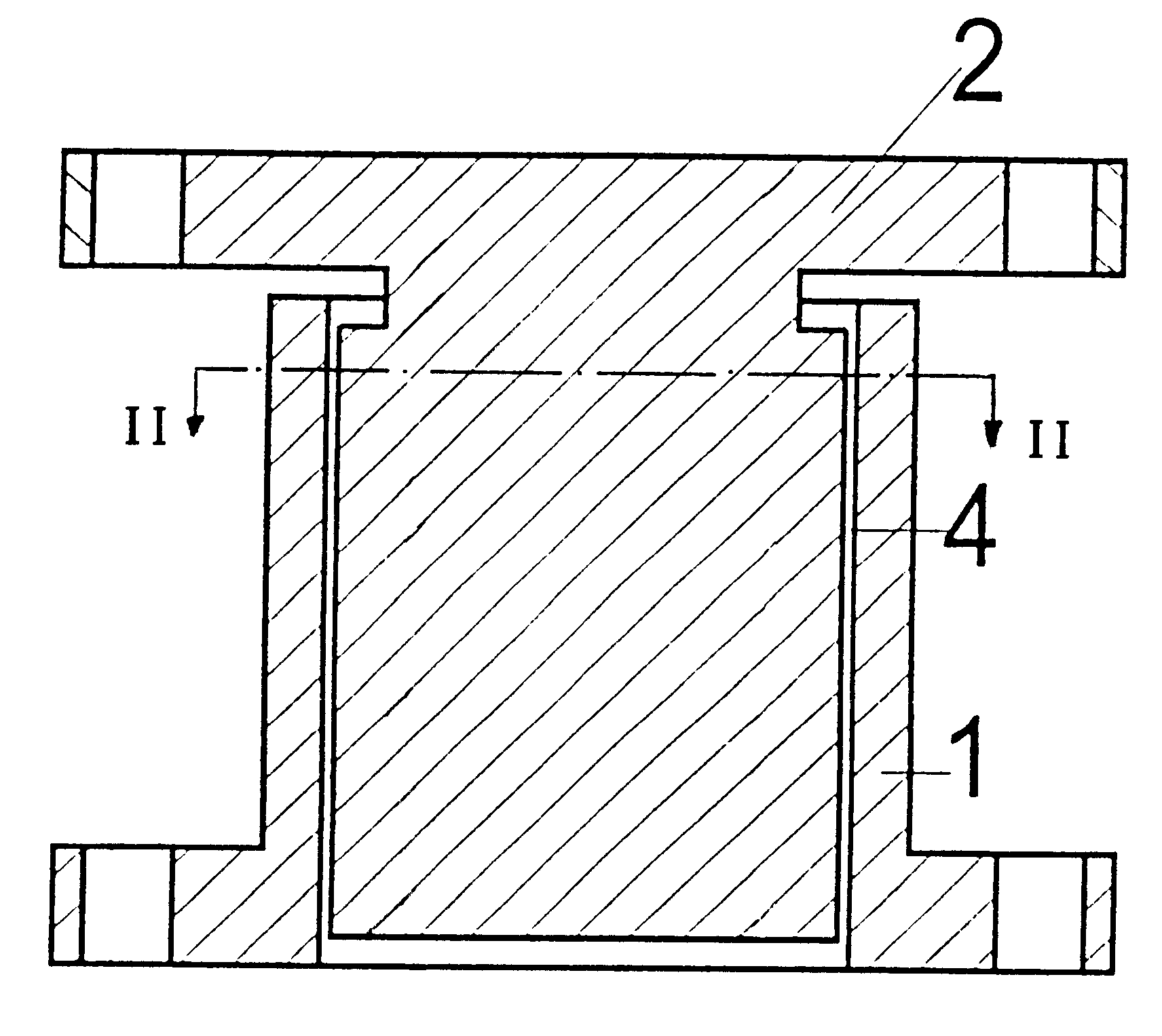
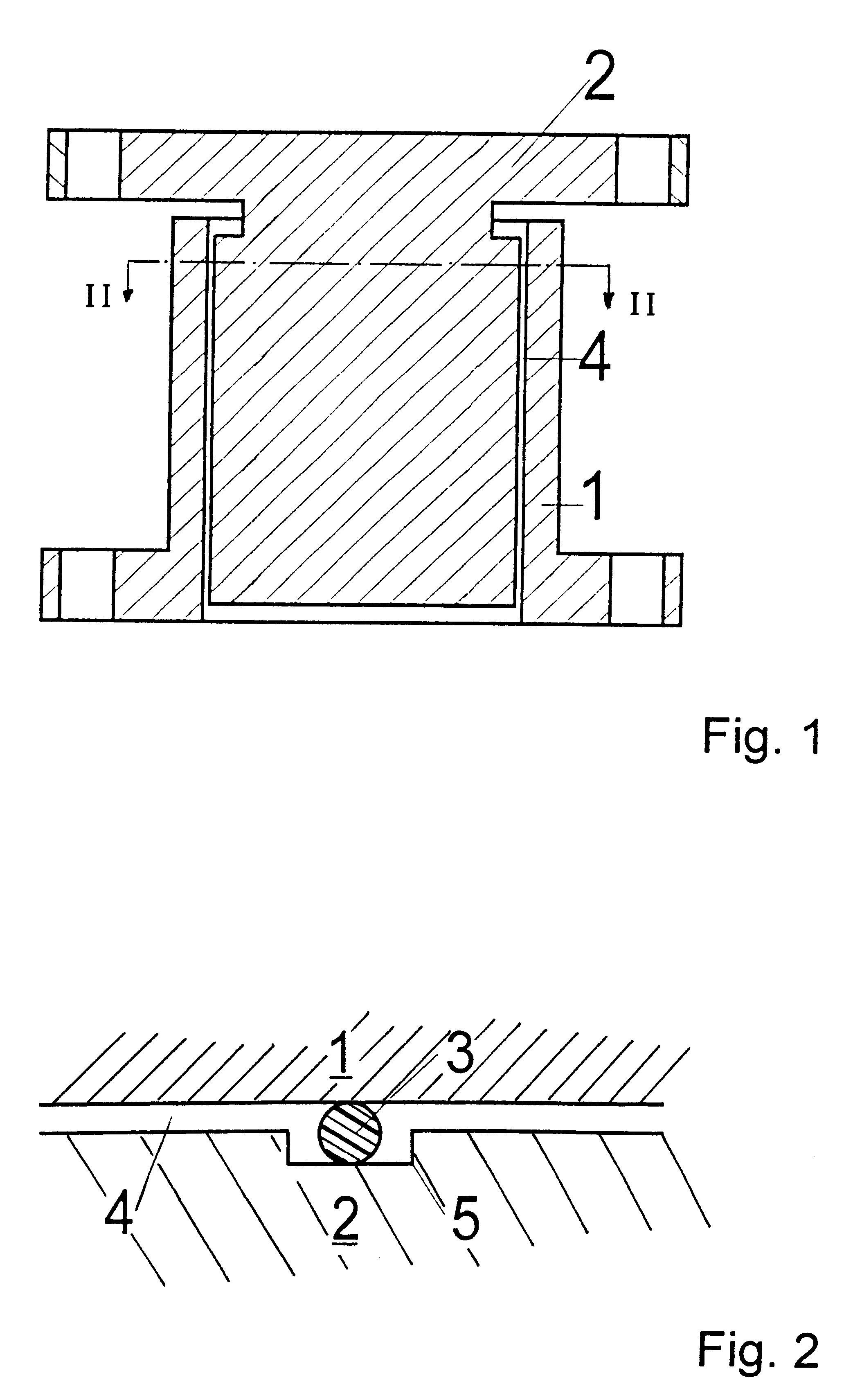
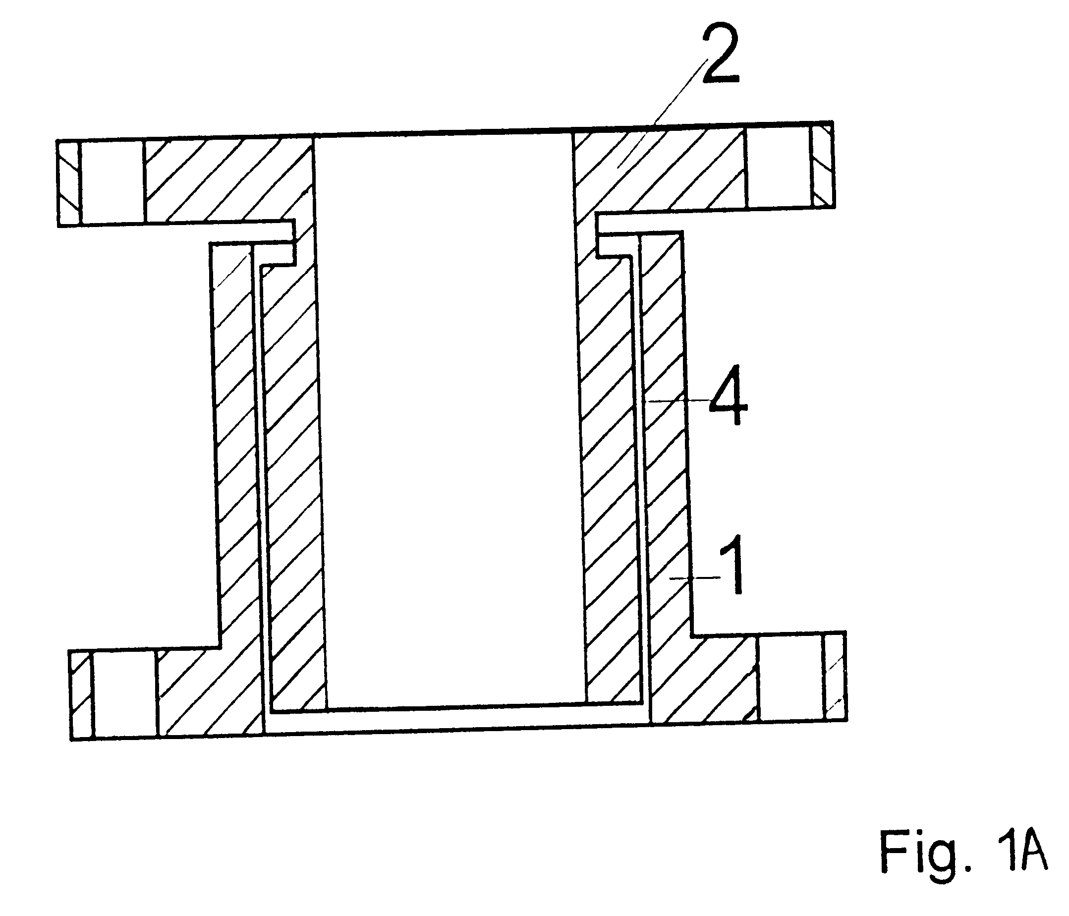
The heat flow switch according to the invention comprises an outer hollow cylinder 1 and an inner body 2. In FIG. 1, the inner body 2 is a solid body, while FIG. 1A shows an alternative embodiment in which the inner body 2 is a hollow cylinder. As shown in FIG. 2, spacers 3 ensure an even annular gap 4 between the inner body 2 and the outer cylinder 1. For practical considerations, at least three spacers 3 are evenly distributed about the circumference of the inner body 2 in longitudinal grooves 5. The spacers 3 consist of an elastic material such as, for example, nylon or Teflon.

The hollow cylinder 1 is advantageously made of copper and thus possesses a linear thermal expansion coefficient .alpha..sub.D =17 ppm / K and a thermal conductivity .lambda.=401 W / (m*K). The inner body 2 consists of molybdenum with an expansion coefficient of .alpha..sub.d =5.1 ppm / K and a thermal conductivity .lambda.=138 W / (m*K). These values are referenced to the ambient temperature.

FIG. 3 shows two refri...


PUM


Abstract

Self-triggering cryogenic heat flow switches are used particularly with cooling systems that require a redundant operation. The self-triggering cryogenic heat flow switch has the simplest possible construction while providing a reliable, maintenance-free mode of operation, and ensures a self-switching connection between a heat sink and an end use device or application that is to be cooled. The heat flow switch includes an outer hollow cylinder 1 that is connected with a heat sink 9, and an inner body 2 that is arranged coaxially to the outer hollow cylinder 1 and connected to the end use device or application to be cooled. When the heat sink 9 is switched off, a concentric annular gap 4 fixed by spacers is provided between the hollow cylinder 1 and the inner body 2. The linear thermal expansion coefficient of the outer cylinder 1 is greater than that of the inner body 2, so that the outer cylinder 1 contracts into thermally conducting contact with the inner body 2 when the heat sink 9 is switched on to provide cooling.

Description

The invention relates to self-triggering cryogenic heat flow or heat flux switches that are used particularly with cooling systems that require a redundant operation.BACKGROUND INFORMATIONIn satellite communications technology, maintenance-free refrigerator-cooled electronic systems (antennas, high temperature superconducting filters, amplifiers) are already being used and will be used increasingly in the future. Such systems must be constructed to provide a service life of several years. The refrigerators are subject to wear in operation and, therefore, in order to avoid a system failure, at least one other refrigerator must be provided as a redundancy. During operation, this redundant refrigerator must be thermally isolated from the end use device or application, since it otherwise acts as a parasitic heat bridge, and must be thermally coupled with the application when the primary cooling refrigerator fails. At the same time, the defective primary refrigerator must be thermally is...

Claims


Application Information

Patent Timeline
IPC IPC(8): B64G1/46B64G1/50F25D19/00F25B9/14
CPCB64G1/50B64G1/506F25D19/006F25B9/14F25B2400/06F28F2013/008
Inventor BINNEBERG, ARMINKAISER, GUNTER
Owner INST FUER LUFT & KAELTETECHNIK GEMEINNUETZIGE GMBH
Why Eureka
Try Eureka