File driven mask insertion for automatic test equipment test pattern generation

a test pattern and automatic testing technology, applied in error detection/correction, program control, instruments, etc., can solve the problems of signal failure of verification step, negative margin time, and small company that often does not have such equipmen

Inactive Publication Date: 2001-10-23
BELL SEMICON LLC
View PDF8 Cites 28 Cited by
  • Summary
  • Abstract
  • Description
  • Claims
  • Application Information

AI Technical Summary

Problems solved by technology

While many large scale businesses can afford the necessary equipment to manufacture their ICs, a small company often does not have such equipment.
Negative margin times are undesirable because the output signal's state is unknown during strobe.
Thus, a negative margin time will cause a signal to fail the verification step.
Small positive margin times close to zero may also be undesirable even though they will not cause a verification failure.
Thus, if an actual IC having only a two nanosecond left margin time outputs data three nanoseconds past the expected output time, it will fail the associated test cycle.
Various design, manufacturing, and operational conditions can cause a manufactured IC's performance to deviate from its ideal performance.
The wafers at the ends of the furnace may be heated to a lower temperature than the wafers in the middle of the furnace, causing small process changes that can result in device operating characteristic differences, including timing variations.
The smaller the margin time becomes for a given test pattern, the higher the failure rate will be due to inevitable IC timing variations.
Non-critical test cycles with short margin times are therefore undesirable since there is a greater likelihood that timing drifts will cause an IC to fail during test, even though the IC would still meet the design's requirements.
However, since an ATE syst...

Method used


Image

  • File driven mask insertion for automatic test equipment test pattern generation
  • File driven mask insertion for automatic test equipment test pattern generation
  • File driven mask insertion for automatic test equipment test pattern generation

Examples


Embodiment Construction

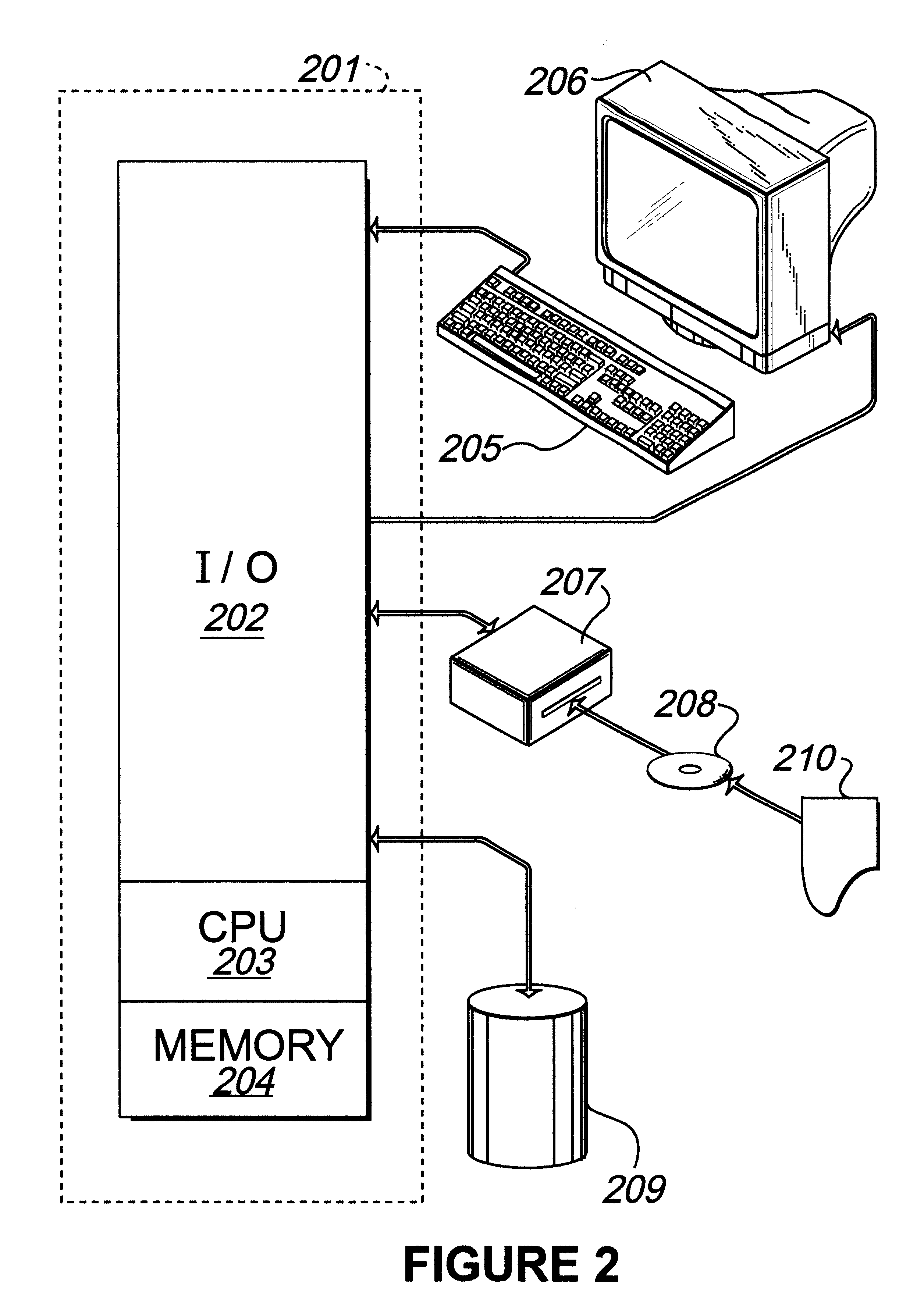
One operating environment in which the present invention is potentially useful encompasses the general purpose computer. In such a system, data and program files may be input to the computer, which reads the files and executes the programs therein. Some of the elements of a general purpose computer are shown in FIG. 2, wherein a processor 201 is shown having an input / output (I / O) section 202, a Central Processing Unit (CPU) 203, and a memory section 204. The present invention is optionally implemented in software devices loaded in memory 204 and / or stored on a configured CD-ROM 208 or storage unit 209 thereby transforming the computer system in FIG. 2 to a special purpose machine for implementing the present invention.

The I / O section 202 is connected to keyboard 205, display unit 206, disk storage unit 209, and disk drive unit 207. Generally, in contemporary systems, the disk drive unit 207 is a CD-ROM driver unit capable of reading a CD-ROM medium 208, which typically contains prog...


PUM


Abstract

A method, system, and program for selectively testing output signals of an integrated circuit. The system comprising a mask generation file specifying output signals and test cycles and a verification module to check simulation output data and generate test pattern data. The verification module further comprising an extractor routine which receives the mask generation file and processes the simulation output data such that the test pattern data is coded to mask the specified output signals at the specified test cycles. The verification module further comprising margin analysis for determining if margin times of the coded test patterns fall below a minimum margin time setting.

Description

1. Field of the InventionThis invention relates to error detection of a semiconductor device, and more particularly to generating a test pattern for testing systems.2. Description of Related ArtMicroelectronic integrated circuits (ICs), such as computer chips, are used in a variety of products including personal computers, automobiles, communication systems, and consumer electronics products. Typically, an IC contains millions of microscopic electrical components and is fabricated on wafers of silicon. As the popularity of ICs has increased, techniques for designing ICs, such as Computer Aided Design (CAD), have become simpler and more economical.The lowered cost of designing ICs allows smaller high-tech companies to create their own custom made, or Application Specific ICs (ASICs), instead of using "off-the-shelf" generic IC packages. While many large scale businesses can afford the necessary equipment to manufacture their ICs, a small company often does not have such equipment. Th...

Claims


Application Information

Patent Timeline
IPC IPC(8): G01R31/28G01R31/3183
CPCG01R31/318307
Inventor FUSCO, GENE T.
Owner BELL SEMICON LLC
Why Eureka
Try Eureka