
Motor for rotating a disk-shaped information recording medium in a disk drive apparatus

a technology of disc drive and information recording medium, which is applied in the direction of sliding contact bearings, record information storage, instruments, etc., can solve the problems of inability to use sintered metal oil-retaining bearings, disadvantageous motors,

Inactive Publication Date: 2001-11-13
SONY CORP
View PDF10 Cites 45 Cited by
  • Summary
  • Abstract
  • Description
  • Claims
  • Application Information

AI Technical Summary

Benefits of technology

It is another object of this invention to provide an improved motor for rotating an information recording medium in a disk drive apparatus which eliminates use of expensive sintered metal oil retaining bearings.
It is a further object of the present invention to provide a motor for rotating an information recording medium in a disk drive apparatus which can rotate both a higher-capacity information recording medium and a lower-capacity information recording medium at different speeds.
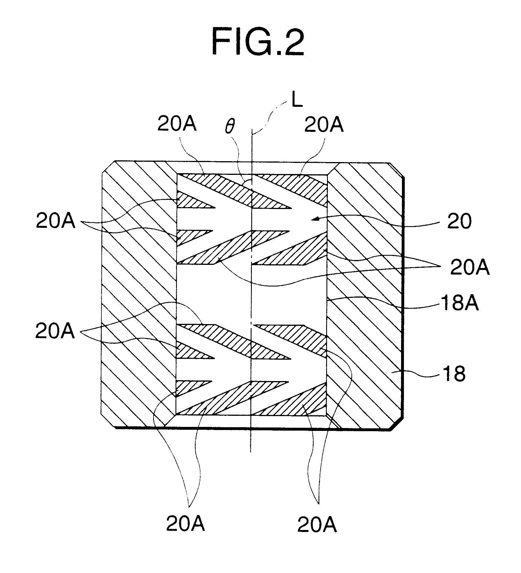
In particular, the bearing functions as a sliding bearing in the case of a lower-capacity medium. In the case of a higher-capacity medium, the bearing enables highly accurate rotation by virtue of a dynamic pressure effect that is obtained by the dynamic pressure generation section.

Problems solved by technology

Although this motor has higher axial deviation accuracy than a conventional motor using the sintered metal oil-retaining bearing, this motor is disadvantageous in cost because of the use of the ball bearing (i.e., bearing 108) which is expensive.
However, the sintered metal oil-retaining bearing cannot be used, in itself, in a high-capacity FDD that is required to have high axial deviation accuracy to cope with a small track pitch.

Method used


Image

  • Motor for rotating a disk-shaped information recording medium in a disk drive apparatus
  • Motor for rotating a disk-shaped information recording medium in a disk drive apparatus
  • Motor for rotating a disk-shaped information recording medium in a disk drive apparatus

Examples


Embodiment Construction

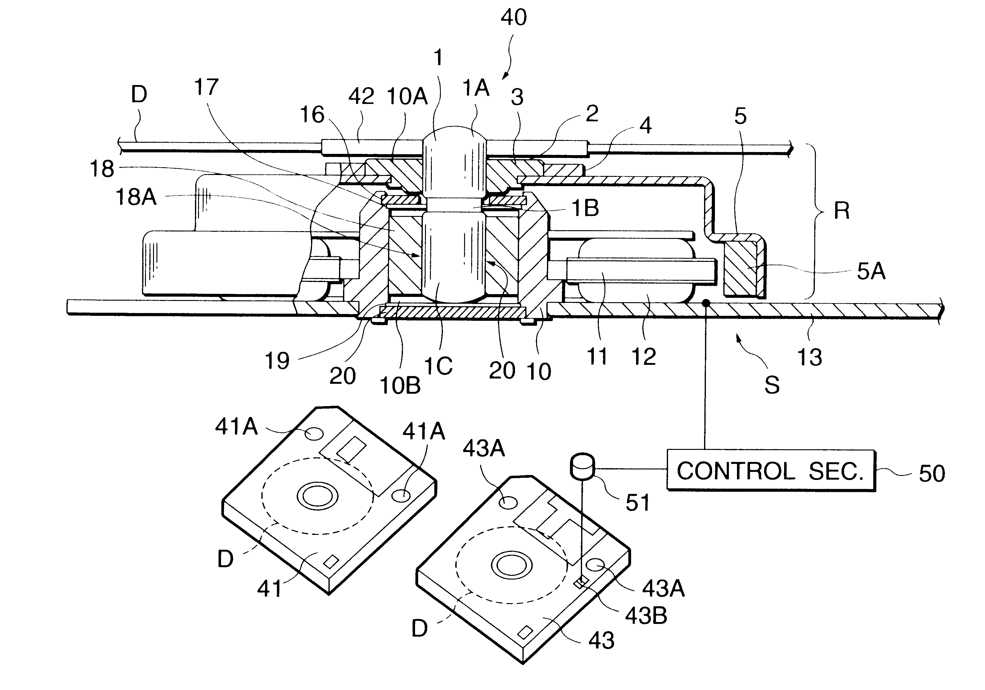
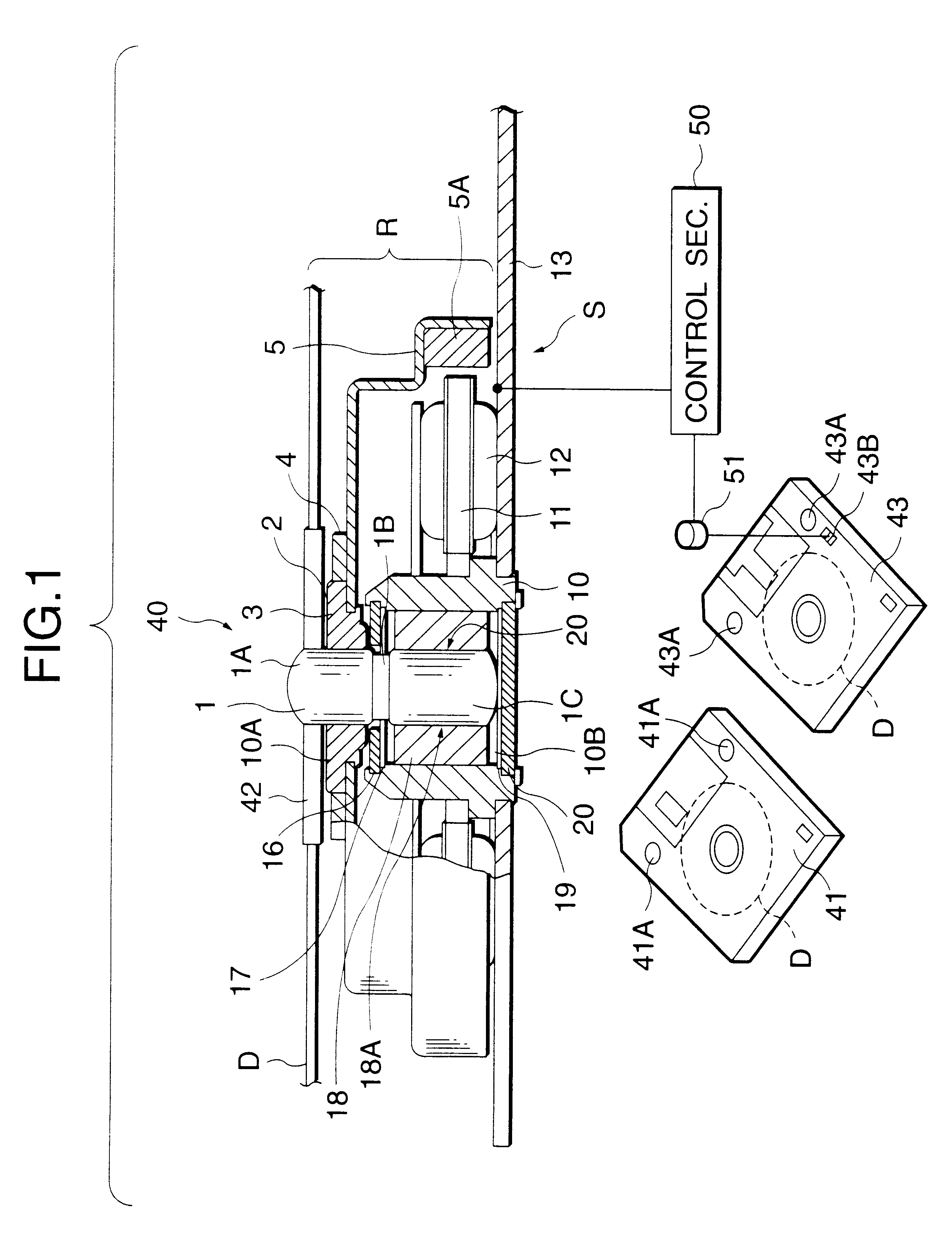
Referring now to FIGS. 1-2, a preferred embodiment of a motor 40 for rotating a disk-shaped information recording medium in a disk drive apparatus in accordance with the teachings of the present invention is illustrated. As is shown therein, the motor 40, which is what is called a spindle motor, has a rotor assembly R, a stator assembly S, and other components. The rotor R can rotate continuously around the stator S with a shaft 1 as the center of rotation.

The rotor assembly R includes a shaft 1, a disk hub seating sheet 2, a boss 3, a disk chucking magnet 4, and a rotor case 5. One end portion 1A of the shaft 1 is shaped in approximately a semi-spherical shape, and the shaft 1 is formed with a recess 1B at a middle position thereof extending over the entire circumference. A lower end portion 1C of the shaft 1 is also shaped in a generally semi-spherical shape. The shaft 1 is supported rotatably in such a manner as to be supported by a bearing 18 in the radial direction and by a thr...


PUM

PropertyMeasurementUnit
dynamic pressureaaaaaaaaaa
speedaaaaaaaaaa
rotation speedaaaaaaaaaa

Abstract

A motor for rotating a disk-shaped information recording medium for a disk drive apparatus which is capable of rotating a higher-capacity information recording medium and a relatively lower-capacity recording medium at different speeds. This motor includes a stator; a rotor that rotates with respect to the stator with a shaft as the center of rotation when a drive winding is energized; a bearing that is provided on the side of the stator and rotatably supports the shaft of the rotor; a dynamic pressure generation section for generating dynamic pressure by filling a fluid between the bearing and the shaft when the shaft is rotated above a predetermined speed; a judging member for judging whether the disk-shaped information recording medium that is attached to the rotor is a relatively lower-capacity medium or a higher-capacity medium; and a control section for supplying the drive winding of the stator with a drive signal for a first rotation speed when a judgment signal produced by the judging member indicates the relatively lower-capacity medium, and with a drive signal for a second rotation speed that is higher than the first rotation speed when the judgment signal indicates the higher-capacity medium.

Description

A. Field of the InventionThe present invention relates to a motor for rotating a disc-shaped information recording medium in a disk drive apparatus. The present invention further relates to a motor for rotating a magnetic recording medium, such as a floppy disk, in a disk drive apparatus.B. Related ArtFloppy disk drives (hereinafter abbreviated as FDDs) that are commonly used as computer peripheral equipment use a disk having an unformatted capacity of about 2 MB per disk. In recent years, disk drives are known which are capable of driving a high-capacity floppy disk having a capacity of more than 100 MB per disk which enable a high data transfer rate.In general, the bearing of a spindle motor for an ordinary FDD that uses only a disk of about 2 MB is a sintered metal oil-retaining bearing (also called simply a metal bearing or an oil-retaining bearing) which is inexpensive. This bearing is formed by compression-molding and then sintering a copper-type or iron-type metal powder, and...

Claims


Application Information

Patent Timeline
Patent Type & Authority Patents(United States)
IPC IPC(8): F16C33/10F16C33/04H02K7/08G11B19/12G11B19/28H02K5/16
CPCF16C17/026F16C17/107F16C33/107H02K7/085F16C2370/12
Inventor KUSAKI, KENJIKIMURA, TORU
Owner SONY CORP
Learn More