Parallel optical fiber amplifier with high power conversion

a technology of parallel optical fiber and amplifier, applied in the field of parallel optical fiber amplifier, can solve the problems of low power conversion efficiency, low pumping efficiency, and high-power pumping requirements, and achieve the effect of high power conversion efficiency

Inactive Publication Date: 2001-11-13
SAMSUNG ELECTRONICS CO LTD
View PDF6 Cites 38 Cited by
  • Summary
  • Abstract
  • Description
  • Claims
  • Application Information

AI Technical Summary

Benefits of technology

is to provide an optical fiber amplifier that exhibits high power conversion efficiency in wide wavelength bands.

Problems solved by technology

In association with L-band EDFAs, there are many pending problems to be solved due to a short history in the development of L-band EDFAs.
For example, L-band EDFAs have low power conversion efficiency and thus require high-power pumps.
Due to such low pumping efficiency of L-band EDFAs, the silica-based optical fiber amplifiers with an L-band EDFA in a parallel configuration have a limitation in its application in the wide bands.

Method used


Image

  • Parallel optical fiber amplifier with high power conversion
  • Parallel optical fiber amplifier with high power conversion
  • Parallel optical fiber amplifier with high power conversion

Examples


Embodiment Construction

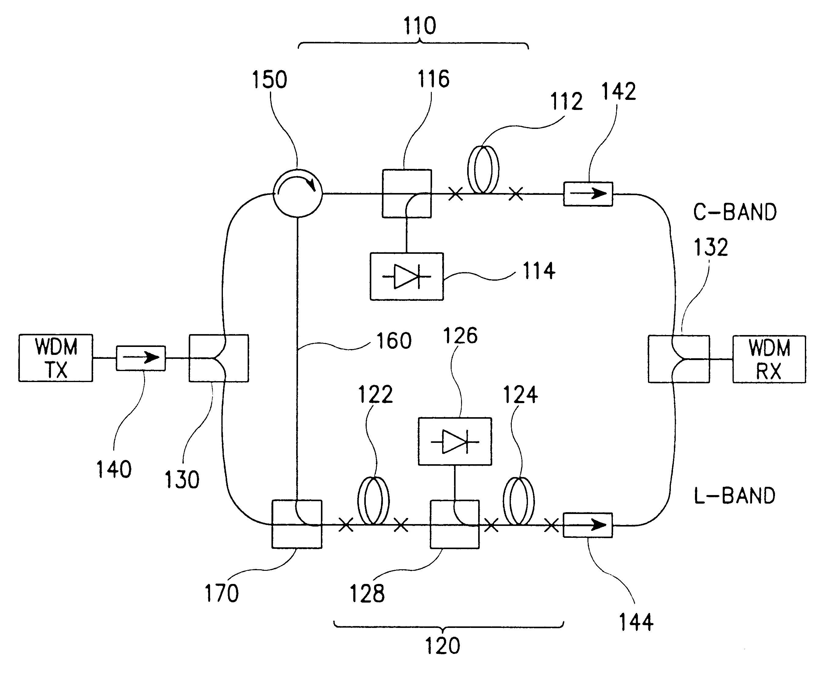
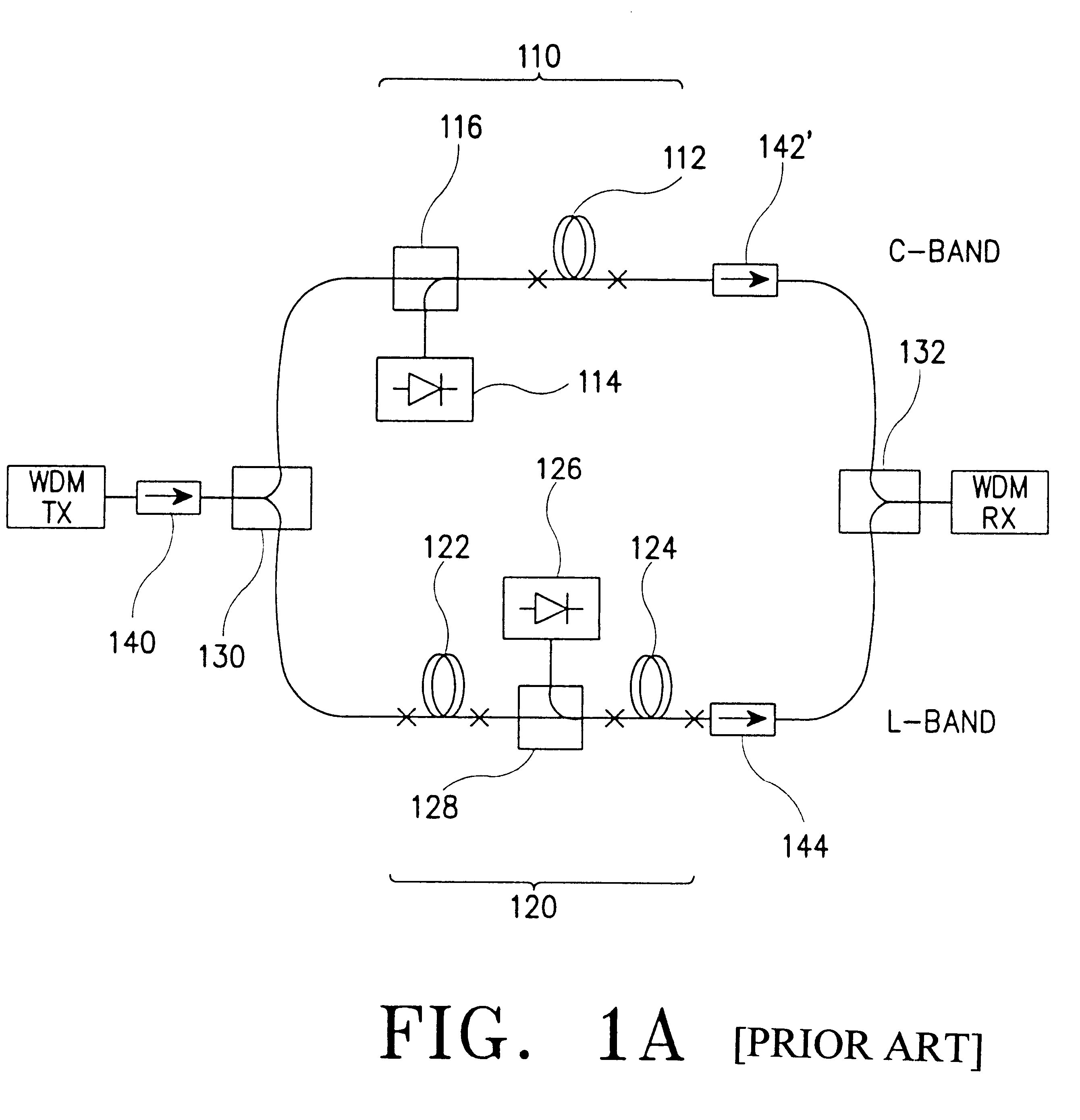
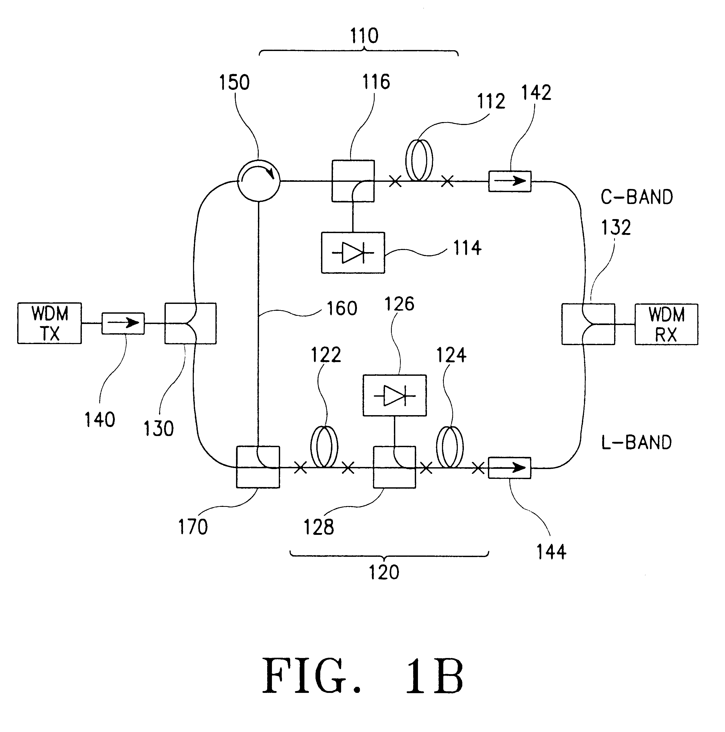
The following description will be made while comparing a parallel optical fiber amplifier according to an embodiment of the present invention with a conventional optical fiber amplifier in terms of the configuration and performance, for easy identification for effects obtained by the embodiment of the present invention.

In FIG. 1a illustrating the conventional parallel optical fiber amplifier, a C-band silica-based EDFA stage 110 and an L-band silica-based EDFA stage 120 are connected to each other in parallel by C-band / L-band WDM couplers 130 and 132, respectively. The C-band EDFA stage 110 includes a C-band EDF 112 having a predetermined length, and a first laser diode 114 for outputting the pumping light of 980 nm to the C-band EDF 112. The first laser diode 114 is coupled to the C-band EDF 112 via a first WDM coupler 116.

In contrast, the L-band EDFA stage 120 includes two EDFs 122 and 124 connected together in series, and a second laser diode 126 coupled between these EDFs 122 an...


PUM


Abstract

A parallel optical fiber amplifier having a configuration in which a C-band silica-based erbium-doped fiber amplifier (EDFA) stage and an L-band EDFA stage are coupled together in parallel in such a fashion that a reverse amplified spontaneous emission (ASE) light emitted from the C-band and / or L-band EDFA stage is reused as a secondary pumping source for an amplification in the L-band EDFA stage. In the optical fiber amplifier of the present invention, the reverse ASE light emitted from the C-band EDFA stage and the reverse ASE light emitted from the L-band EDFA stages supplied to the L-band EDFA stage so that they can be reused for improving the power conversion efficiency of the entire system and for reducing the noise factor thereof.

Description

CLAIM OF PRIORITYThis application makes reference to, incorporates the same herein, and claims all benefits accruing under 35 U.S.C. .sctn. 119 arising from an application entitled, PARALLEL OPTICAL FIBER AMPLIFIER WITH HIGH POWER CONVERSION, filed earlier in the Korean Industrial Property Office on Nov. 24, 1998, and there duly assigned Ser. No. 1998-50407.1. Field of the InventionThe present invention relates to an optical device for optical communications, and more particularly to a parallel optical fiber amplifier having a configuration capable of reusing an amplified spontaneous emission (ASE) light as a secondary pumping source.2. Description of the Related ArtCurrently, Er.sup.3+ -doped fiber amplifiers (EDFAs) having a wide gain band have been proposed to increase the capability of wavelength division multiplexed (WDM) systems to meet the continued demand for higher capacity. For the practical systems using such EDFAs, it has been regarded as inevitably necessary to use sili...

Claims


Application Information

Patent Timeline
Patent Type & Authority Patents(United States)
IPC IPC(8): H01S3/067H01S3/06H01S3/094H01S3/23G02B6/00G02B6/02H01S3/0915H01S3/10
CPCH01S3/06754H01S3/06766H01S3/0677H01S3/094003H01S3/2383G02B6/00
Inventor PARK, NAM-KYOOLEE, JU-HANRYU, UH-CHAN
Owner SAMSUNG ELECTRONICS CO LTD
Why Eureka
Try Eureka