Engine control strategy using dual equal cam phasing combined with exhaust gas recirculation

Inactive Publication Date: 2001-11-27
FORD MOTOR CO
View PDF7 Cites 44 Cited by
  • Summary
  • Abstract
  • Description
  • Claims
  • Application Information

AI Technical Summary

Benefits of technology

It is an objective of the invention to combine the advantages of using dual equal variable camshaft timing for achieving exhaust gas recirculation at low and moderate engine loads with the advantages of using an external exhaust gas recirculation system at higher engine loads. In this way, the external exhaust gas recirculation system may

Problems solved by technology

Further, decreased pumping losses during the intake and exhaust strokes of the engine also res

Method used


Image

  • Engine control strategy using dual equal cam phasing combined with exhaust gas recirculation
  • Engine control strategy using dual equal cam phasing combined with exhaust gas recirculation
  • Engine control strategy using dual equal cam phasing combined with exhaust gas recirculation

Examples


Embodiment Construction

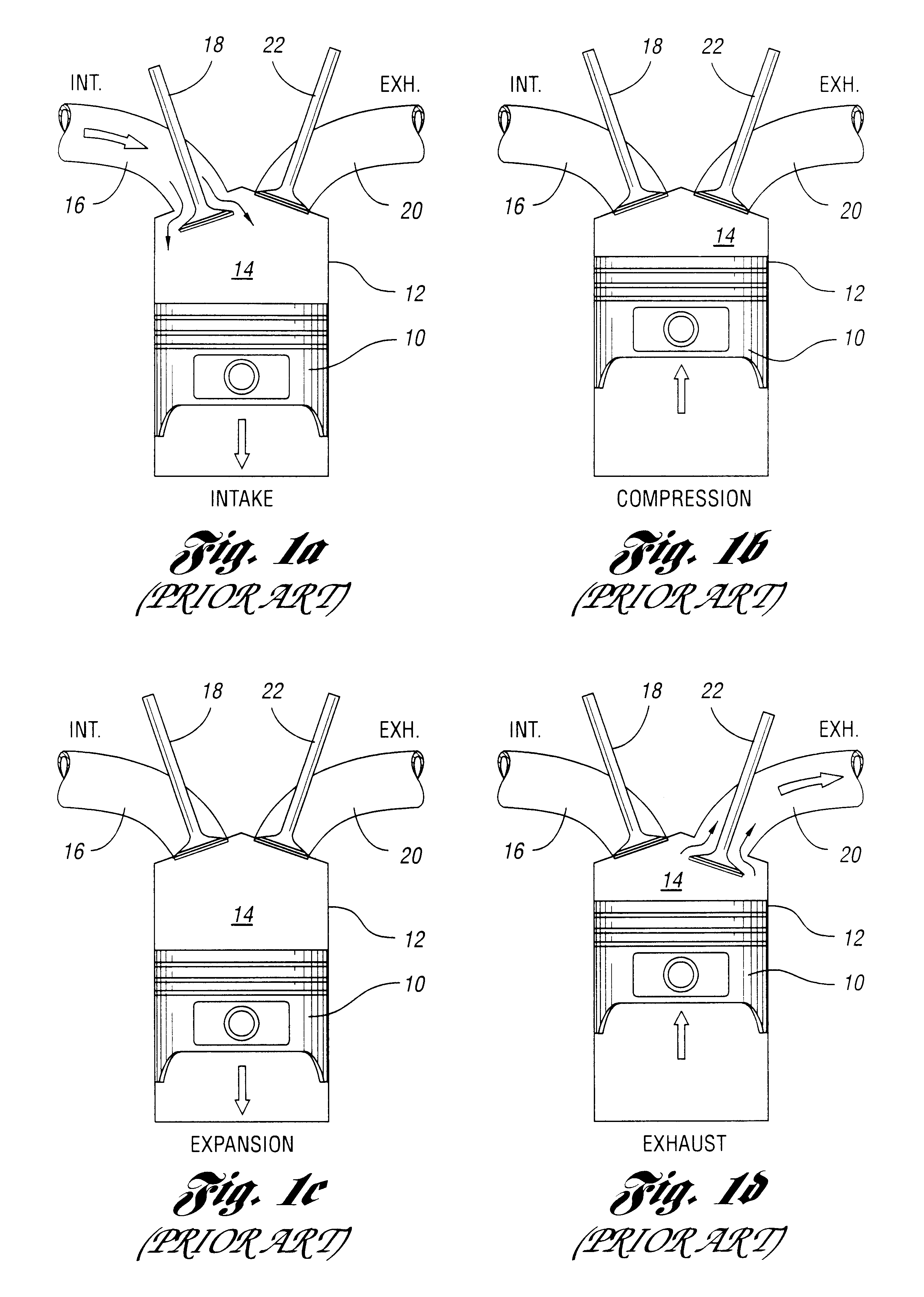
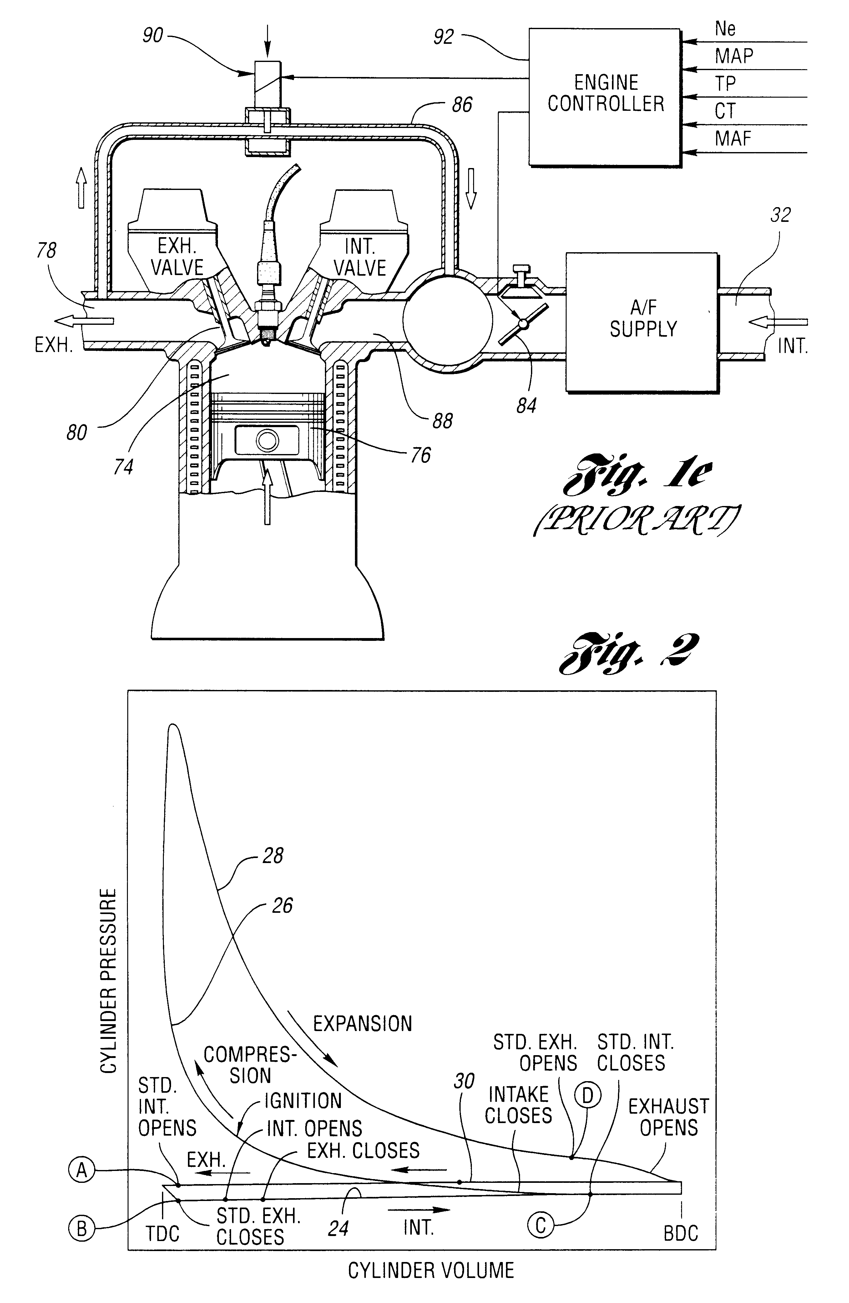
FIGS. 1a, 1b, 1c, 1d and 1e show schematically a conventional four stroke cycle engine having one or more cylinders. One of the engine cylinders is illustrated in FIG. 1a in the intake mode, in FIG. 1b in the compression mode, in FIG. 1c in the expansion mode, and in FIG.1d in the exhaust mode. In FIGS. 1a-1d, piston 10 and cylinder 12 define a combustion chamber 14. The piston 10, which is connected to a crankshaft in known manner, moves downward in the cylinder 12 during the intake stroke, as shown by the directional arrow in FIG. 1a. During the intake stroke, air or an air / fuel mixture is drawn into the combustion chamber from intake passage 16. The flow is controlled by intake valve 18. An exhaust port 20 communicates with the combustion chamber 14 through an exhaust valve 22.

During the compression stroke, which is indicated in FIG. 1b, the piston moves upward, thereby compressing the charge in combustion chamber 14. At that time, the intake valve 18 and the exhaust valve 22 are...


PUM


Abstract

The invention comprises a strategy and method for phase shifting intake and exhaust valve timing relative to crankshaft position as a function of engine operating variables, whereby valve overlap is delayed to obtain improved fuel economy resulting from a late intake valve closing to reduce pumping work during the intake stroke. The exhaust gases are drawn into the combustion cylinder of the engine during the intake stroke, which reduces oxides of nitrogen in the exhaust gas and reduces unburned hydrocarbons. Improved thermal efficiency and reductions in oxides of nitrogen are achieved as the combustion charge is diluted at higher loads by an external exhaust gas recirculation system, thereby combining the effects of exhaust gas recirculation and dual equal variable camshaft timing to obtain fuel economy benefits that cannot be achieved with either a conventional EGR system acting alone or dual equal variable camshaft timing acting alone.

Description

A control strategy for controlling internal combustion engines, particularly for controlling valve timing relative to crankshaft position.A conventional internal combustion engine, such as a four stroke cycle engine typically used in passenger vehicles, uses an exhaust gas recirculation system for reducing emissions of oxides of nitrogen. In such systems, the exhaust gas is recirculated back to the combustion chamber thus reducing peak combustion temperature. Because formation of oxides of nitrogen increases as combustion temperature increases, the presence of exhaust gas in the combustion chamber reduces oxides of nitrogen.It is known design practice to obtain exhaust gas recirculation by altering the valve timing normally associated with a four stroke OTTO cycle internal combustion engine. Internal exhaust gas recirculation will result from the overlap in the operation of the intake valve and the operation of the exhaust valve (i.e., the intake valve is open while the exhaust valv...

Claims


Application Information

Patent Timeline
IPC IPC(8): F02D13/02F02M25/07
CPCF02D13/0215F02D13/0219F02D13/0261F02D13/0269F02M25/0715F02M25/0752F02D2013/0292Y02T10/121Y02T10/142F02M26/13F02M26/01Y02T10/12
Inventor RUSS, STEPHEN GEORGESTEIN, ROBERT ALBERT
Owner FORD MOTOR CO
Why Eureka
Try Eureka