Jig for fitting locks to doors

a technology for fitting locks and doors, which is applied in the direction of sawing apparatus, drilling machines, instruments, etc., can solve the problems of easy movement during marking operations, inability to guarantee the accuracy of subsequent drilling or other operations, and time-consuming operation of fixing a mortise lock or a cylindrical lock to a door, so as to facilitate the alignment of the jig and eliminate the damage to the door

Inactive Publication Date: 2002-02-05
ZIVOJINOVIC ZARKO
View PDF11 Cites 44 Cited by
  • Summary
  • Abstract
  • Description
  • Claims
  • Application Information

AI Technical Summary

Benefits of technology

A screw member acting through each of the four arms of the pair of forks, perpendicular to the plane of the door and operating against the respective guide plate in that vicinity is thus able to independently adjust the position of and consequently in co-operation with the corresponding screw member on the opposite side of door to which the jig is to be affixed, clamp the respective guide plates against opposing sides of the door when the jig is thus located along the edge thereof. Therefore the guide plates are clamped to the door during use, the only other contact being the point or line of contact along the centre of the edge of the door for locating the forks as described above. Thus damage to the door is eliminated by virtue of the use of relatively large guide plates affixed in thi

Problems solved by technology

Conventionally, fixing a mortise lock or a cylindrical lock to a door is a time consuming operation.
However, one of the major problems in using a stencil or paper template is that it can easily move during the marking operation.
Furthermore, once the positions are marked, there is no guarantee that subsequent drilling or other operations would be performed accurately.
Consequently, there is a likelihood that not only will locks be fitted at varying heights, but that, worse still, they will be fitted somewhat out of alignment causing undue stress on the lock mechanism.
In addition, there is a high likelihood that damage will occur to the door not only during the operation of marking out the location of the lock but more importantly as a result of slippage of tools whilst performing the various drilling and mortising functions.
This is particularly true when considering the difficulties encountered whilst installing a mortise lock.
Naturally, during the process of preparing the mortise, there is a likelihood that the relevant cutting tool will slip, whether it be a router, drill bit, chisel etc, thereby causing it to tear or break through this thin-walled section with generally unrepairable consequences.
Although it is generally known to employ various jigs for carpentry and joinery, in order to facilitate drilling, routing and other operations, these do not specifically address the particular problems encountered in preparing the mortise for mortise locks and/or the other relevant holes etc for such locks or even preparing the relevant holes for cylindrical locks.
Even where jigs have been developed which are

Method used


Image

  • Jig for fitting locks to doors
  • Jig for fitting locks to doors
  • Jig for fitting locks to doors

Examples


Embodiment Construction

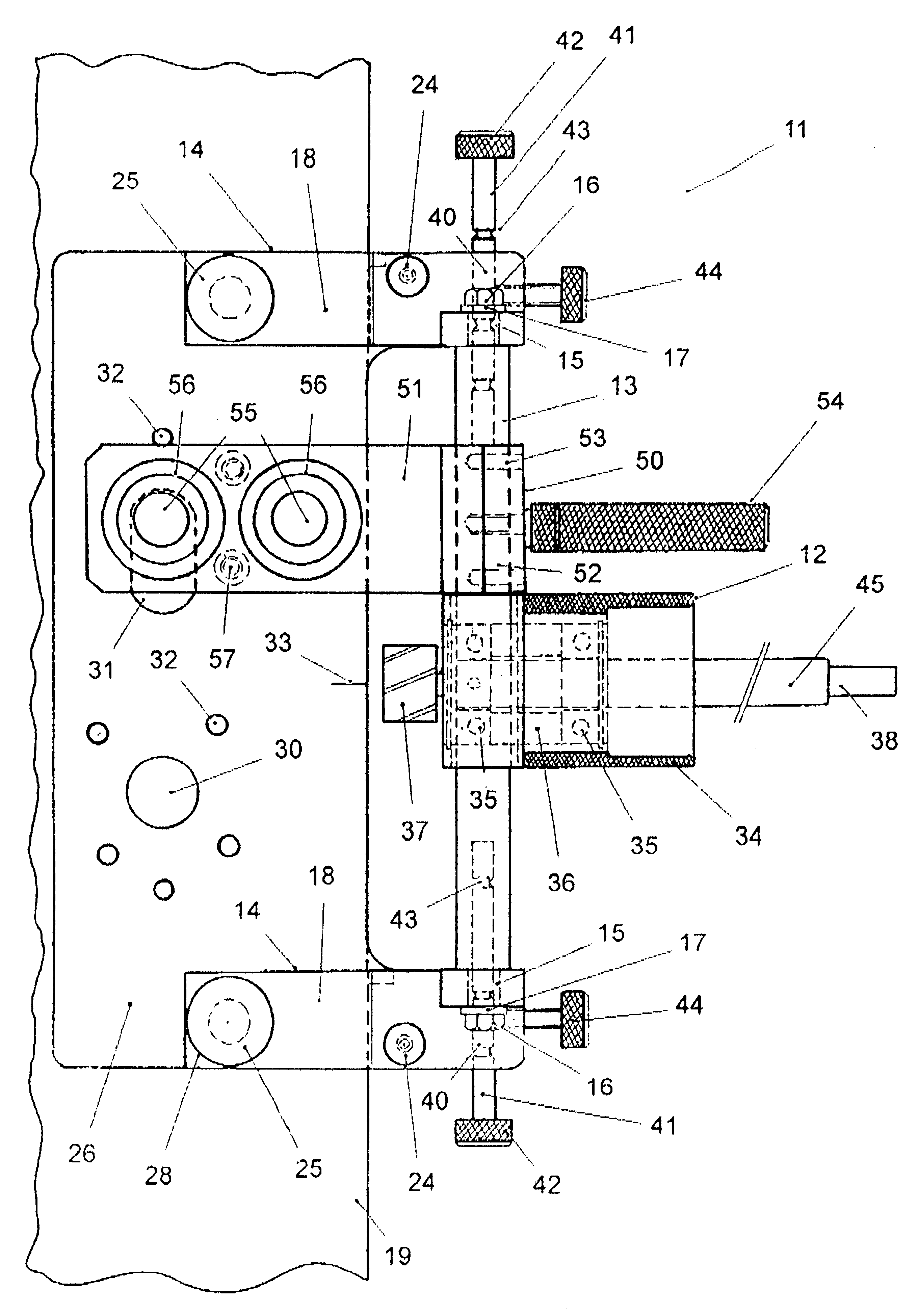
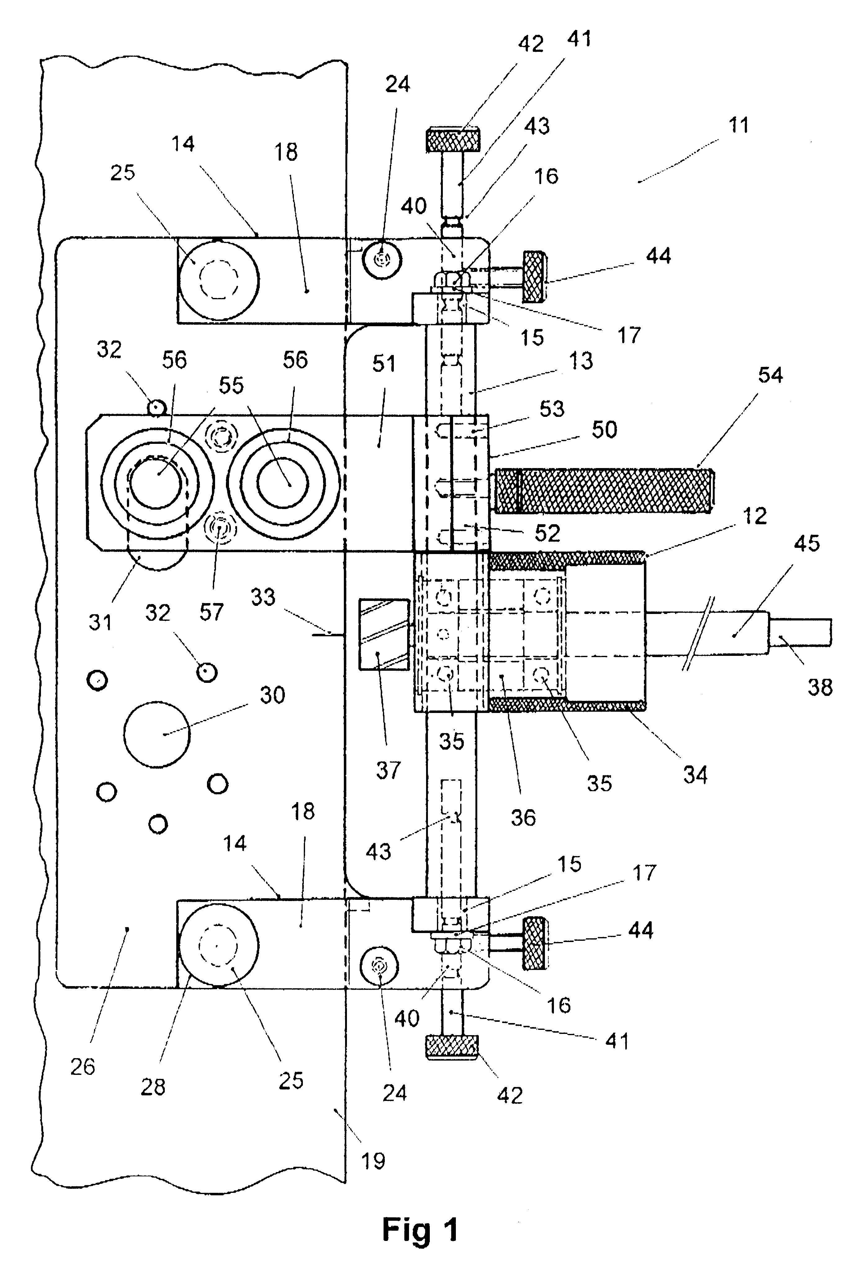
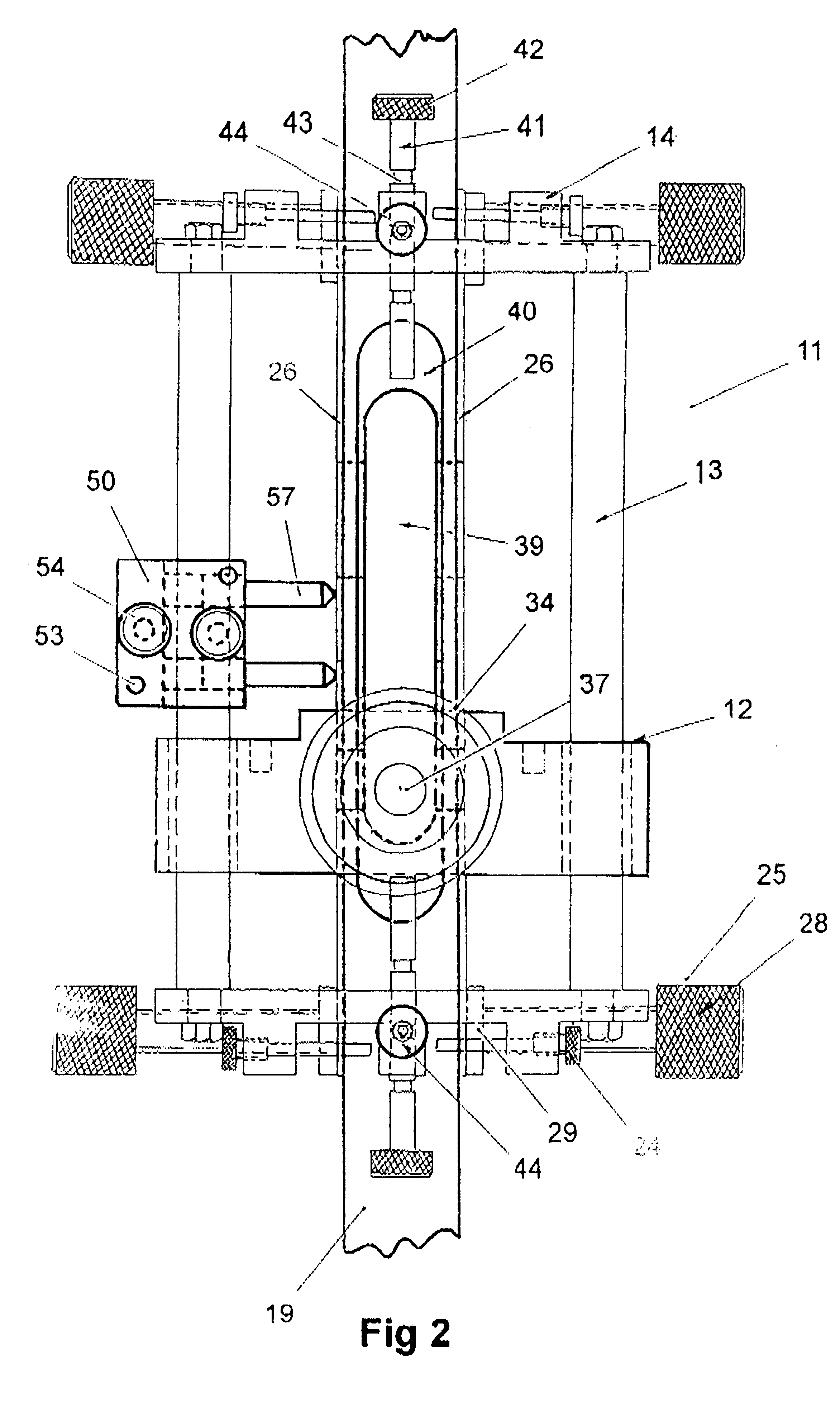
Referring generally to FIGS. 1 and 2 there is illustrated a jig, generally referenced 11, for preparing a door to receive a lock, in this case a mortise lock (not illustrated), according to a preferred embodiment of the invention.

Jig 11, comprises a sliding block 12, mounted on a pair of support rails 13, which extend between and are fixedly attached to a pair of fork members 14. The detail of the fork members 14 on their own is also shown in FIG. 3. The fork members 14 are provided with holes 15 through which the ends of the support shafts 13 are attached to the fork members 14 by means of nuts 16 and washers 17.

The fork members 14, each have a pair of arms 18 which extend in use over the surface of a door 19 to which the jig 11 is to be fitted. Located centrally between the respective arm 18 of each of the fork members 14 is a central portion 20 which is provided at its upper extremity with a v-shaped portion 21 which acts as a centring guide and which in use prevents the bulk of ...


PUM

PropertyMeasurementUnit
Lengthaaaaaaaaaa
Widthaaaaaaaaaa
Distanceaaaaaaaaaa

Abstract

A jig (11) for removable fitment along the edge of a door (19) which provides a suitable combination of guides and stops to allow the location and operation of suitable cutting tools such as drills or routers. The jig comprises a pair of parallel guide plates (26) the distance between which is adjustable for removable fitment to opposing surfaces of the door. Guide holes (30, 31, 32) are located in the guide plates through which a drill or other suitable tool may be inserted. The jig has guide means (12) associated therewith for allowing location of a suitable tool at the edge of the door for making a cylindrical hole or for machining a mortise therein for receiving the body of a mortise lock or a rebate for receiving the face plate of the lock mechanism. A guide block (50) to facilitate accurate drilling is also disclosed.

Description

This invention relates to means for affixing locks in doors, and in particular relates to an adjustable jig suitable for affixing temporarily along the edge of a door for guiding the cutting action of suitable cutting tools such as drills and / or routers and the like in order to make appropriate holes or recesses in the door for receiving the lock mechanism.Conventionally, fixing a mortise lock or a cylindrical lock to a door is a time consuming operation. Firstly, it is necessary to mark the location of the various holes and recesses on the side and edge of the door into which the lock mechanism must be fitted. Typically, this is achieved by using a suitable stencil, for example a paper stencil, to mark the various locations where drilling and other operations such as routing etc must be carried out. Using these markings, various tools are then employed to create a mortise in the edge of the door to receive the body of a mortise lock or a cylindrical hole to receive the bolt of a cy...

Claims


Application Information

Patent Timeline
IPC IPC(8): B23B47/28B23B47/00B27F5/12B27F5/00E05B17/06E05B17/00
CPCB23B47/287B27F5/12E05B17/06Y10T408/567Y10T408/98
Inventor ZIVOJINOVIC, ZARKO
Owner ZIVOJINOVIC ZARKO
Why Eureka
Try Eureka