Digital servo control system for use in disk drives

a technology of servo control system and disk drive, which is applied in the direction of maintaining head carrier alignment, recording information storage, instruments, etc., can solve the problems of slowing down read or write operations, changing the orientation of the disk drive, and increasing the read/write error rate, so as to achieve stable tracking and efficient seeking

Inactive Publication Date: 2002-02-12
MAXTOR +1
View PDF15 Cites 173 Cited by
  • Summary
  • Abstract
  • Description
  • Claims
  • Application Information

AI Technical Summary

Benefits of technology

The present invention provides a highly adaptive, responsive, comprehensive servo control system allowing stable tracking and efficient seeking in the presen

Problems solved by technology

These anomalies may involve aging, temperature changes, changes in orientation of the disk drive, humidity, shock and vibration.
If these goals are not met, misalignment or delayed alignment of the read/write heads with respect to the tracks cause increases in read/write errors and a slowdown in read or write operations.
As recording densities improve, a hindering factor in reducing overall disk drive physical dimensions may be the size of the circuitry required to implement the servo system.
This "dedicated" scheme has the disadvantage that it occupies a substantial portion of the total area allotted for useful information.
As the physical size of disks becomes smaller with the progress of technology, dedication of an entire disk surface to servo information becomes increasingly unacceptable.
Although embedded servo designs have increased the servo area efficiency over dedicated schemes, known embedded servo schemes have typically involved complex servo data fields, which has forced larger amount

Method used


Image

  • Digital servo control system for use in disk drives
  • Digital servo control system for use in disk drives
  • Digital servo control system for use in disk drives

Examples


first embodiment

. FIGS. 2 and 3 are the highest level functional diagrams for the first embodiment, FIG. 4 providing the highest level flow chart. FIGS. 5A-10 detail certain functions performed in FIGS. 2, 3 or 4.

SECOND EMBODIMENT. FIG. 12 is the highest level functional diagram for the second embodiment, with FIGS. 13 and 14 being the highest level flow diagrams. FIGS. 14-30 detail certain functions performed in FIGS. 12, 13, or 14.

BEST MODES FOR CARRYING OUT THE INVENTION

In describing preferred embodiments of the present invention illustrated in the drawings, specific terminology is employed for the sake of clarity. However, the invention is not intended to be limited to the specific terminology so selected, and it is to be understood that each specific element includes all technical equivalents which operate in a similar manner to accomplish a similar purpose. Certain elements may be omitted from the drawings and text for clarity or brevity, as they have structures and functions known to those s...

second embodiment

A second embodiment of the invention is described with special reference to FIGS. 12 and 13. The description of this embodiment is provided in the following order:

Functional Descriptions:

Servo Field Structure (FIG. 16)

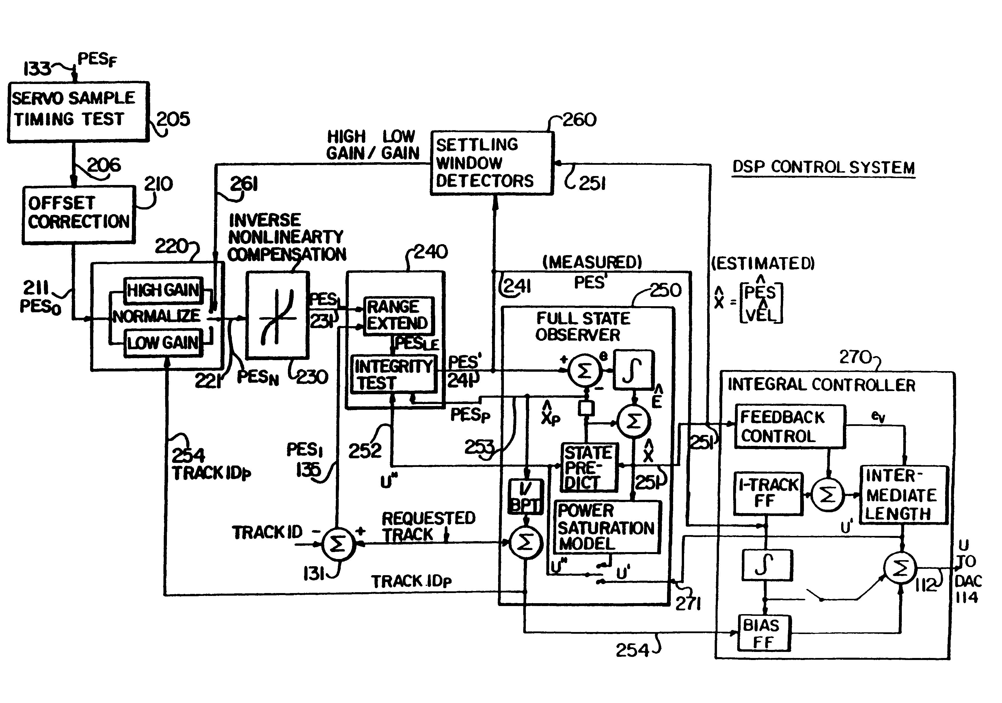
DSP Control System (FIG. 12)

Servo Timing Test

Offset Correction (FIGS. 17A, 17B)

Gain Normalization (FIGS. 18A, 18B)

Inverse Nonlinearity Compensation (FIG. 19)

Range Extension; Integrity Test (FIGS. 20A-20C)

Power Amplifier Model (FIGS. 21A, 21B)

Observer (FIG. 22)

Settling Window Detectors (FIGS. 23A, 23B, 23C)

Integral Controller (FIGS. 24, 25)

Single Track FF Controller (FIGS. 26A, 26B)

Bias Feedforward Controller (FIG. 27)

Intermediate Length Feedforward Controller (FIGS. 28A, 28B, 28C)

Re-calibration (FIG. 29)

Dynamic Scaling of Parameters (FIG. 30)

Description of Sequential Steps:

High-level Flow Chart (FIG. 13)

High-level Timing Diagram (FIG. 14)

Phases Experienced During Seeks (FIG. 15)

Command Routines

Control Routines

Subroutines

Window Routines

Post Processing Routines

Calibratio...


PUM


Abstract

A digital servo control system for disk drives is an "embedded" system-one in which servo control information is embedded on the same disk surface as the user data. In contrast to known embedded-servo systems in which a space-consuming series of many dibit pairs is present, the present system provides only a single dibit pair in a fractional positional error (PESF) area. Thus, the disk drive's read head encounters only a single dibit pair per sample period (or per data sector), thus saving valuable disk space that may be used for user data. Various pre-processing methods may be provided so as to pre-process the measurement derived from the single dibit pair per sample period (or data sector), so as to compensate for non-ideal characteristics of the dibit measurement. The system thus provides an accurate and robust servo control system, while sacrificing a minimum amount of valuable disk space to the servo information field.

Description

The present invention related to servo control systems which may be used in controlling the head positioning actuators in storage devices such as disk drives. More specifically, the invention relates to digital servo control systems involving efficient implementations of tracking and seeking servo control methods.BACKGROUND ART AND BACKGROUND OF THE INVENTIONVarious servo control systems are known in the art. U.S. Pat. No. 3,458,785 (Sordello) discloses an early example of a servo control system employing quadrature signals for providing position and velocity information, the system having fine and coarse positioning control algorithms. U.S. Pat. No. 4,135,217 (Jacques et al.) discloses a system which compensates for repeatable errors such as wobble of a disk, with stored "run-out" information being used to compensate for the errors. U.S. Pat. No. 4,412,161 (Cornaby) generally discloses a digitally implemented recursive servo control system. U.S. Pat. No. 4,486,797 (Workman) disclos...

Claims


Application Information

Patent Timeline
IPC IPC(8): G11B21/08G11B21/10G11B5/596G11B5/55
CPCG11B5/5534G11B5/5547G11B5/59616G11B21/10G11B5/5965G11B21/081G11B21/085G11B5/59622
Inventor KADLEC, RONALD JAMESFREDERICK, THOMAS JAMESKELLEY, PAUL HENRYWEILBACHER, PHILIP SAXTON
Owner MAXTOR
Why Eureka
Try Eureka