Wireless fiber-coupled telecommunication systems based on atmospheric transmission of laser signals

a technology of optical fiber and optical fiber, which is applied in the direction of duplex signal operation, instruments, cables, etc., can solve the problems of pstn carrying the triple burden of voice, fax and data communication, severely limited transmission bandwidth to a telephone subscriber, and nearly saturated pstn

Inactive Publication Date: 2002-02-19
SEAFORT INT TRADING SRL +1
View PDF12 Cites 111 Cited by
  • Summary
  • Abstract
  • Description
  • Claims
  • Application Information

AI Technical Summary

Problems solved by technology

Thus, the transmission bandwidth deliverable to a telephone subscriber is severely limited, typically less than 56,600 bits per second.
At present, the PSTN bears the triple burden of conveying voice, fax, and data communications, and is nearly saturated in certain large metropolitan regions.
First time subscribers to ISDN service generally incur a cost for installation of an ISDN line which comprises upgraded copper wire.
Thus, the cost of implementing a fiber optic network may be exorbitant.
In general, all hard-wired networks are burdened with the requirement of laying cable to new subscribers / nodes.
Furthermore, it is difficult to reconfigure the topology of an existing hard-wired network since cables are quite often buried underground, suspended from poles, or stung through the interstitial spaces of office buildings.
Thus, the radio spectrum is increasingly crowded resulting in degraded signal quality and / or increased subscriber costs.
As will become apparent in the following discussion, the binding of all the sub-systems into a commnon chassis effects the design complexity of the communication unit and the installation procedures for the communication unit both of which impact the effective cost to the consumer.
Since, the communication unit includes active electronics, the user / client generally incurs a significant cost for providing a power connection to the installation site.
This cost severely impacts the marketability of existing laser-based systems to home users and small business users.
Humidity from the ambient air may corrode internal metallic parts.
These weather related constraints add to the overall cost of prior art laser-based communication units.
Laser-based communication units are massive and voluminous because of the colocation of transceiver electronics, data interface, and antenna optics in a common chassis.
The cost of designing the chassis and its mounting structures contributes to overall cost of the communication unit.
The additional time required to conduct the random search in case of an insufficiently bore-sighted sighting scope significantly adds to the cost of installation.
Although a sighting scope may be bore sighted initially, e.g. in the factory or by trained personnel at a field site, the bore sighting (i.e. calibration) may be compromised over the passage of time.
For example, thermal stresses and weathering (rain, hail, wind, etc.) may contribute to loss of bore sighting accuracy.
Thus, the cost of bore sighting may be incurred more than once through the lifetime of the laser-based communication unit.
The pressures exerted in removing the access panel and exchanging boards may disturb the LOS of the communication unit.
Thus, the investment in achieving LOS to the remote optical antenna may be lost when accessing electronics for maintenance, repair, and / or upgrade.
This greatly increases the effective cost of repairing or modifying the electronics of the communication unit.
However, the cost of such systems is typically in the $10,000 to $20,000 dollar range, making them unsuitable for most home and business use.

Method used


Image

  • Wireless fiber-coupled telecommunication systems based on atmospheric transmission of laser signals
  • Wireless fiber-coupled telecommunication systems based on atmospheric transmission of laser signals
  • Wireless fiber-coupled telecommunication systems based on atmospheric transmission of laser signals

Examples


Embodiment Construction

Incorporation by Reference

For general information on broadband telecommunications and optical data communications, please see Lee, Kang and Lee, Broadband Telecommunications Technology, Artech House, 1993 which is hereby incorporated by reference in its entirety. Also please see Davis, Carome, Weik, Ezekiel, and Einzig, Fiber Optic Sensor Technology Handbook, Optical Technologies Incorporated, 1982, 1986, Herndon, Va., which is hereby incorporated by reference in its entirety.

Full-Duplex Transceiver System

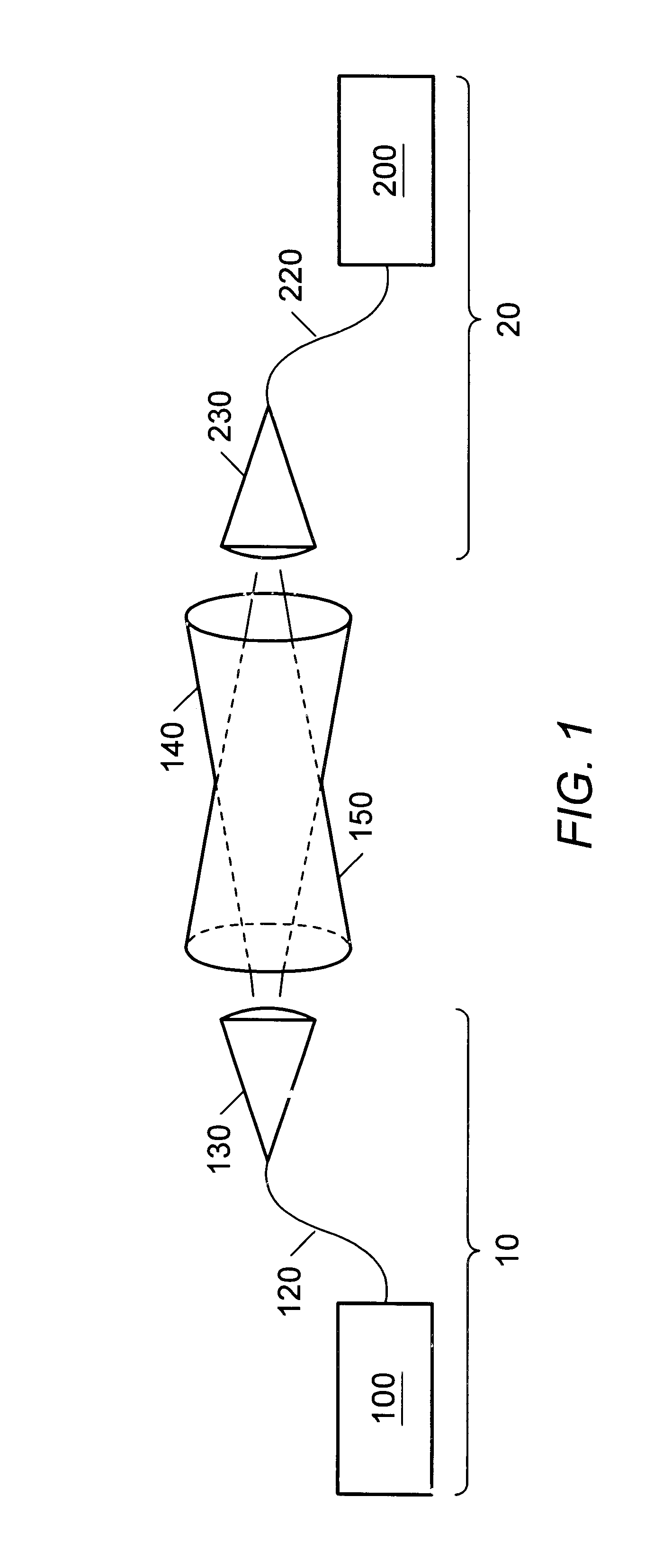
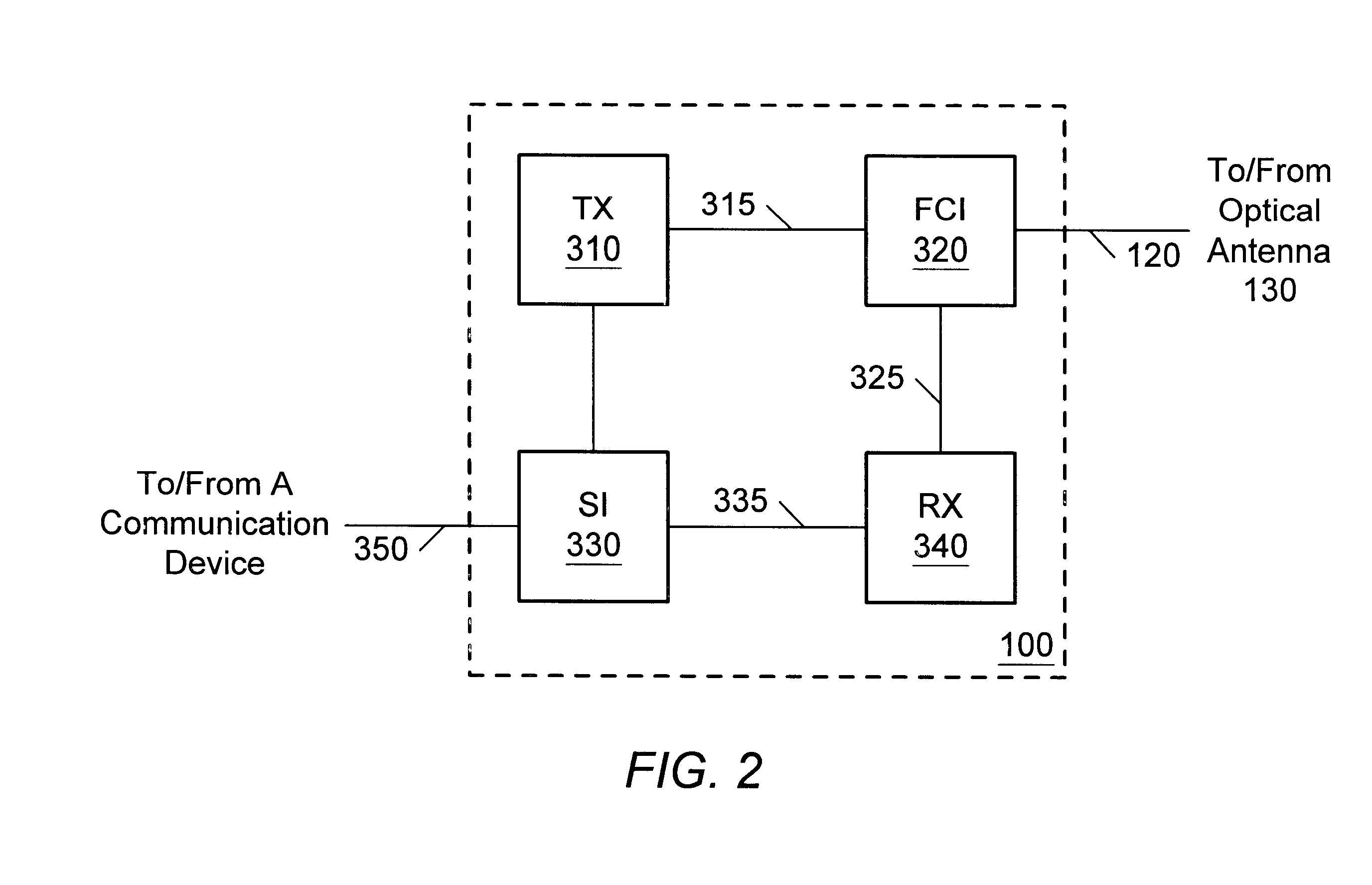
Referring now to FIGS. 1, a fall-duplex transceiver system 10 for light-based wireless communication through the atmosphere is presented. Transceiver 10 includes transceiver electronics module 100 and passive optical antenna 130. The transceiver electronics module 100 is coupled to passive optical antenna 130 through optical fiber 120. Since the optical antenna 130 includes only passive components, no power connection is necessary at the location of optical antenna 130. The user of...


PUM

PropertyMeasurementUnit
distanceaaaaaaaaaa
diameteraaaaaaaaaa
transmissionaaaaaaaaaa

Abstract

A wireless optical transceiver system which includes a passive optical antenna coupled by optical fiber to an active electronics module. The transceiver system receives and transmits light beams from / to the atmosphere,.and thereby communicates optically with a second optical transceiver. Receivers, transmitters, repeaters, switches, routers, etc., may be similarly organized, i.e. by coupling one or more passive optical antennas and an active electronics module with fiber-optic cable. Furthermore, various network toplogies and organizations may be arranged using one or more of the fiber-coupled transceivers, receivers, transmitters, repeaters, switches, routers, etc. Such components are admirably suited for use in various network configurations such as broadcast networks, point-to-multipoint networks, etc due to their low cost, ease of installation and antenna sighting, modularity, and upgradability. An optical router for establishing wireless channels to a number of subscribers may be configured based on demodulation and remodulation of light beams, or alternatively by redirecting light beams by adjustable deflections mirrors. A communications network infrastructure based on atmospheric light beam propagation is contemplated.

Description

The present invention relates generally to wireless telecommunications networks, and more particularly to a broadband telecommunication system and network which employs atmospheric (i.e. free-space) laser transmission.DESCRIPTION OF THE RELATED ARTIn the modern telecommunications market, there exists a vast array of products and services targeted for the needs and desires of consumers at every level. Many of these products and services necessitate a network infrastructure. For example, telephone service is mediated by the Public Switched Telephone Network (PSTN), also known as the Plain Old Telephone System (POTS).Any-to-any connectivity is a fundamental organizing principle of the PSTN, i.e. any telephone subscriber should be able to call and communicate with any other telephone subscriber. The switching systems employed in the PSTN are almost completely digital. Fiber optic cables, copper cables, microwave links, and satellite links are used for data transmission. Transmission ove...

Claims


Application Information

Patent Timeline
Patent Type & Authority Patents(United States)
IPC IPC(8): H04B10/10G02B6/44H01B11/22
CPCG02B6/4405H04L5/16H04B10/1121H04B10/1125H04B10/1127H01B11/22G02B6/4411G02B6/4416G02B6/4459
Inventor DOUCET, MARK A.PANAK, DAVID L.
Owner SEAFORT INT TRADING SRL
Why Eureka
Try Eureka