Power train for use in motor vehicles and the like

a technology for power trains and motor vehicles, applied in the direction of engine-driven generators, propulsion, transportation and packaging, etc., can solve the problems of excessive space requirements of power trains, especially in the axial direction of engine output members, and achieve the effect of enhancing the compactness of power trains

Inactive Publication Date: 2002-03-12
LUK LAMELLEN & KUPPLUNGSBAU BETEILIGUNGS KG
View PDF13 Cites 118 Cited by
  • Summary
  • Abstract
  • Description
  • Claims
  • Application Information

AI Technical Summary

Benefits of technology

An object of the instant invention is to enhance the com

Problems solved by technology

On the other hand, heretofore known power trains which employ an electric machine between the prime mover and the transmission are likely to exhibit the drawback that their space requirements (especially in the axial direction of the output member

Method used


Image

  • Power train for use in motor vehicles and the like
  • Power train for use in motor vehicles and the like
  • Power train for use in motor vehicles and the like

Examples


Embodiment Construction

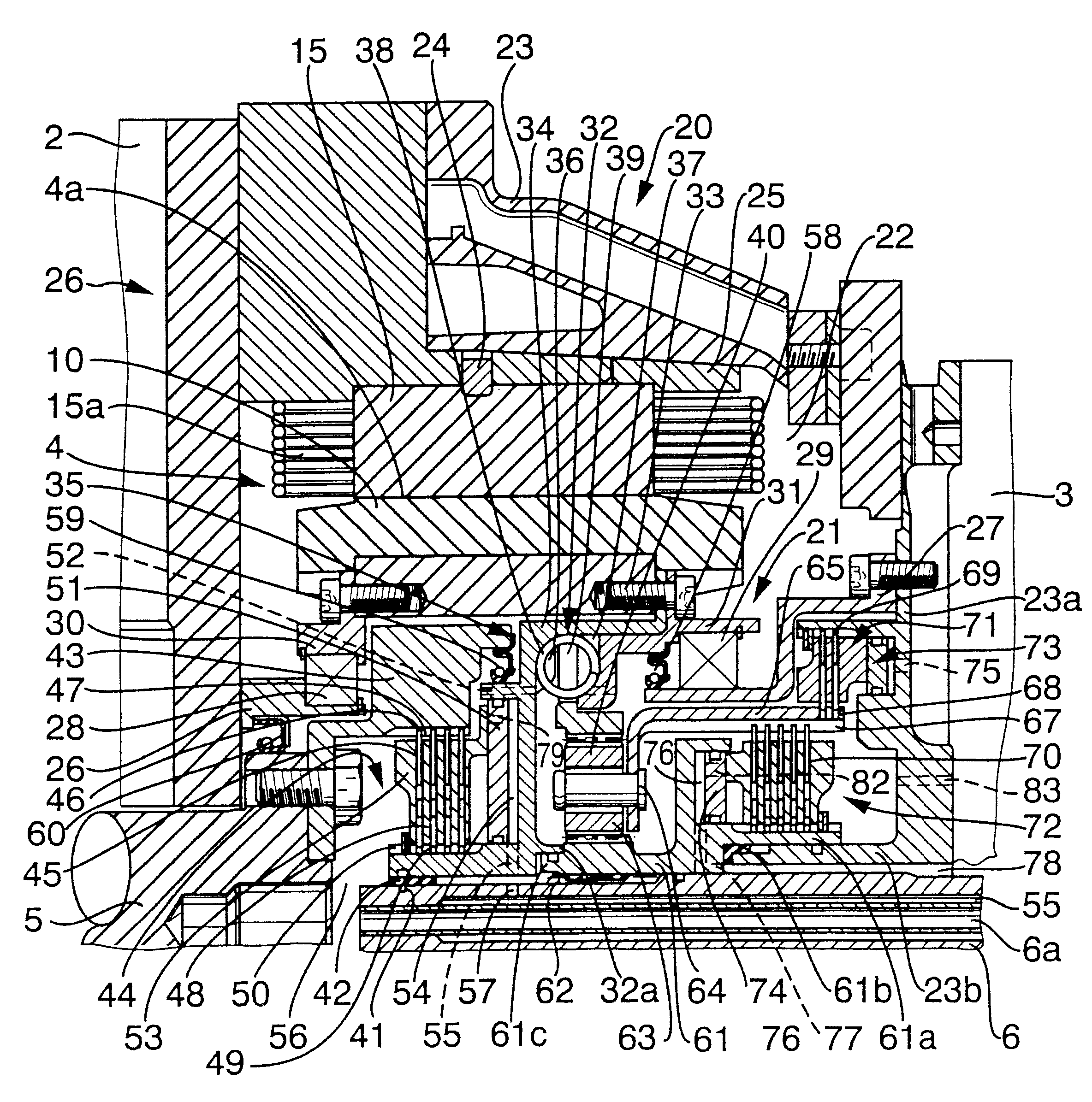
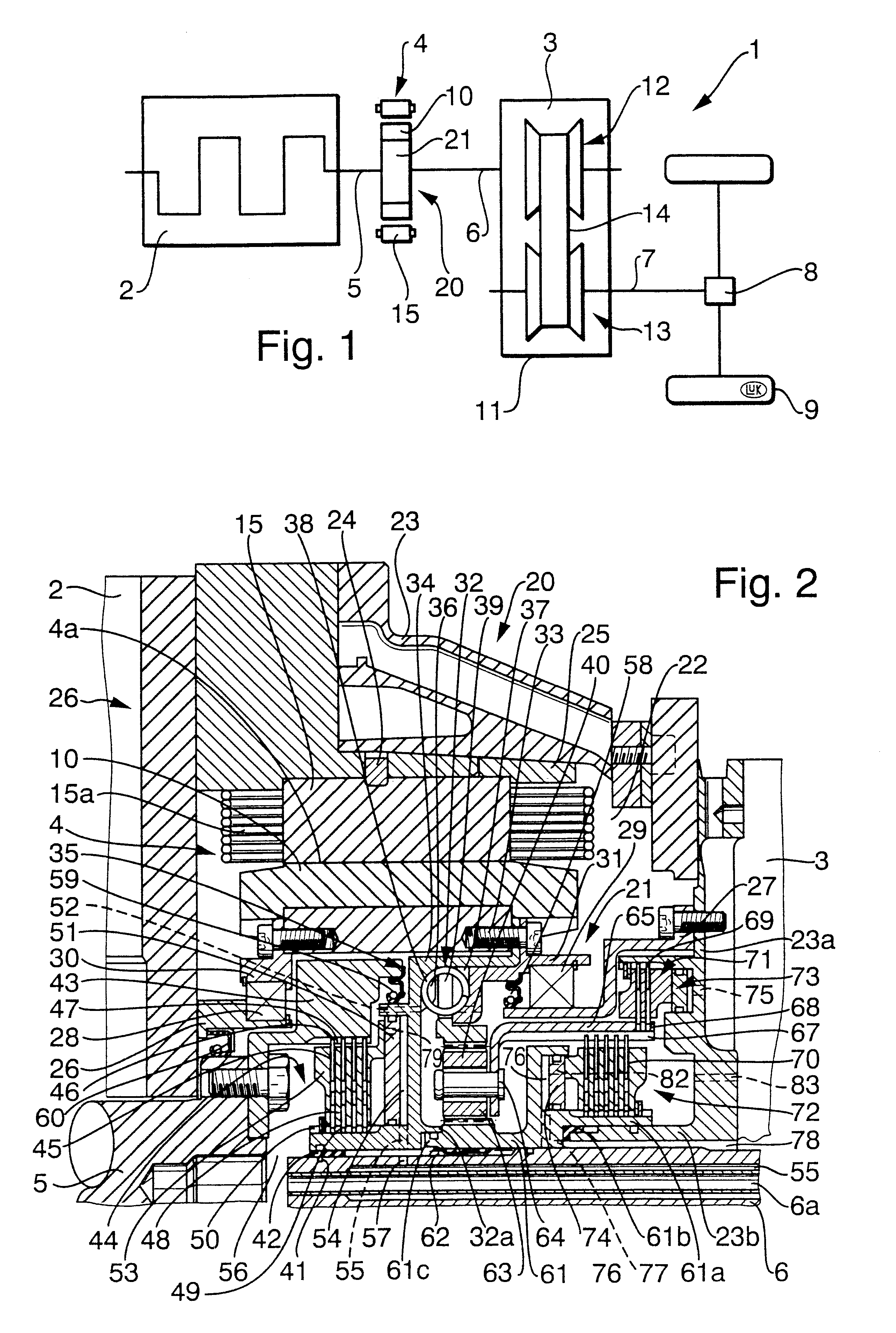
FIG. 1 shows a power train 1 which is installed in a motor vehicle and comprises a prime mover 2 (such as an internal combustion engine) having a rotary output member 5 (e.g., a camshaft or a crankshaft) arranged to drive the coaxial input member (such as a shaft) 6 of a multiple speed ratio transmission 3. The rotary output member 7 of the transmission 3 drives the front and / or rear wheels 9 of the motor vehicle by way of a differential 8. The illustrated transmission 3 is a continuously variable transmission (CVT), e.g., of the type disclosed in commonly owned U.S. Pat. No. 5,217,412 (granted Jun. 8, 1993 to Indlekofer et al.), U.S. Pat. No. 5,667,448 (granted Sep. 16, 1997 to Friedmann) or U.S. Pat. No. 5,711,730 (granted Jan. 27, 1998 to Friedmann et al.). The disclosures of all U.S. and foreign patents and patent applications identified in the specification of the present application (including the German priority application Serial No. 199 18 787.8 filed Apr. 26, 1999) are inc...


PUM


Abstract

The output shaft of a combustion engine and/or the input shaft of a transmission in the power train of a motor vehicle is directly or indirectly connected to or connectable with the rotor of an electric machine. The stator of the electric machine surrounds the rotor and the latter surrounds, at least in part, a gearing and/or a clutch for and/or another constituent of the transmission. Such design contributes to compactness of the power train.

Description

The present invention relates to power trains, especially for use in motor vehicles. More particularly, the invention relates to improvements in power trains of the type wherein a prime mover (such as an internal combustion engine) and a transmission (such as a continuously variable transmission) flank an electric machine having a stator and a rotor surrounded by the stator and operatively connected or connectable with the rotary output member (e.g., a first shaft) of the prime mover and / or with the rotary input member (e.g., a second shaft) of the transmission.Published German patent application Serial No. 196 25 022 discloses a power train wherein the electric machine is coaxial with the output member of the prime mover and is installed axially between the prime mover and the transmission. For example, the electric machine can be put to use during starting of the prime mover (such as a combustion engine) in the power train of a motor vehicle. Alternatively, the electric machine ca...

Claims


Application Information

Patent Timeline
IPC IPC(8): B60K6/00B60K6/04B60K6/02F16H61/66B60K6/26B60K17/04B60K6/365B60K6/387B60K6/40B60K6/48B60K6/543B60K17/06B60K17/08B60L50/16F16D25/0638H02K7/10
CPCB60K6/26B60K6/387B60K6/40B60K6/48B60K6/543B60K6/365Y10S903/918F16H61/66Y02T10/6221Y10S903/902Y10S903/903Y10S903/951Y10S903/909Y10S903/906Y10S903/91Y10S903/914Y10S903/919Y02T10/62
Inventor KOZAREKAR, SHAILESH
Owner LUK LAMELLEN & KUPPLUNGSBAU BETEILIGUNGS KG
Why Eureka
Try Eureka