Method and apparatus for reducing vibrations transmitted to a vehicle from a wheel unit

a technology of reducing vibration and wheel unit, which is applied in the direction of vehicle tyre testing, vehicles, instruments, etc., can solve the problems of unsatisfactory vibrations that are transmitted to other components of the vehicle, unfavorable environmental protection, and time-consuming grinding process, so as to achieve the effect of optimizing the simulation of the road surface, reducing the rotational mass of the roller shoe, and simple and precise positioning of the wheel uni

Inactive Publication Date: 2002-03-26
SCHENCK ROTEC GMBH
View PDF20 Cites 28 Cited by
  • Summary
  • Abstract
  • Description
  • Claims
  • Application Information

AI Technical Summary

Benefits of technology

In another advantageous embodiment the rollers have roller sections of larger and smaller diameters. The sections of larger and smaller diameters on different neighboring rollers are offset or axially displaced so that a section of larger diameter of one roller extends radially into the space provided by a smaller diameter roller section between two larger roller sections on a neighboring roller. This intermeshing arrangement of the rollers makes the roller shoe compact and allows the rollers to be placed in relatively close proximity to each other, whereby the roller sections form a loading surface that contacts the tire tread at many closely spaced points within a single plane thereby optimally simulating a road surface. This arrangement has the further advantage that commercially available ball bearings or roller bearings can be used for forming the roller sections as rotatable roller rings. Particularly the roller sections of larger diameter can be formed as antifriction bearings...

Problems solved by technology

Irregularities in a tire, such as localized variations in the tire elasticity, dimensional deviations, unbalances and other irregularities in the wheel rim and/or tire characteristics of the wheel unit can cause undesirable vibrations that are transmitted to other components of the vehicle.
Vibrations ...

Method used


Image

  • Method and apparatus for reducing vibrations transmitted to a vehicle from a wheel unit
  • Method and apparatus for reducing vibrations transmitted to a vehicle from a wheel unit
  • Method and apparatus for reducing vibrations transmitted to a vehicle from a wheel unit

Examples


Embodiment Construction

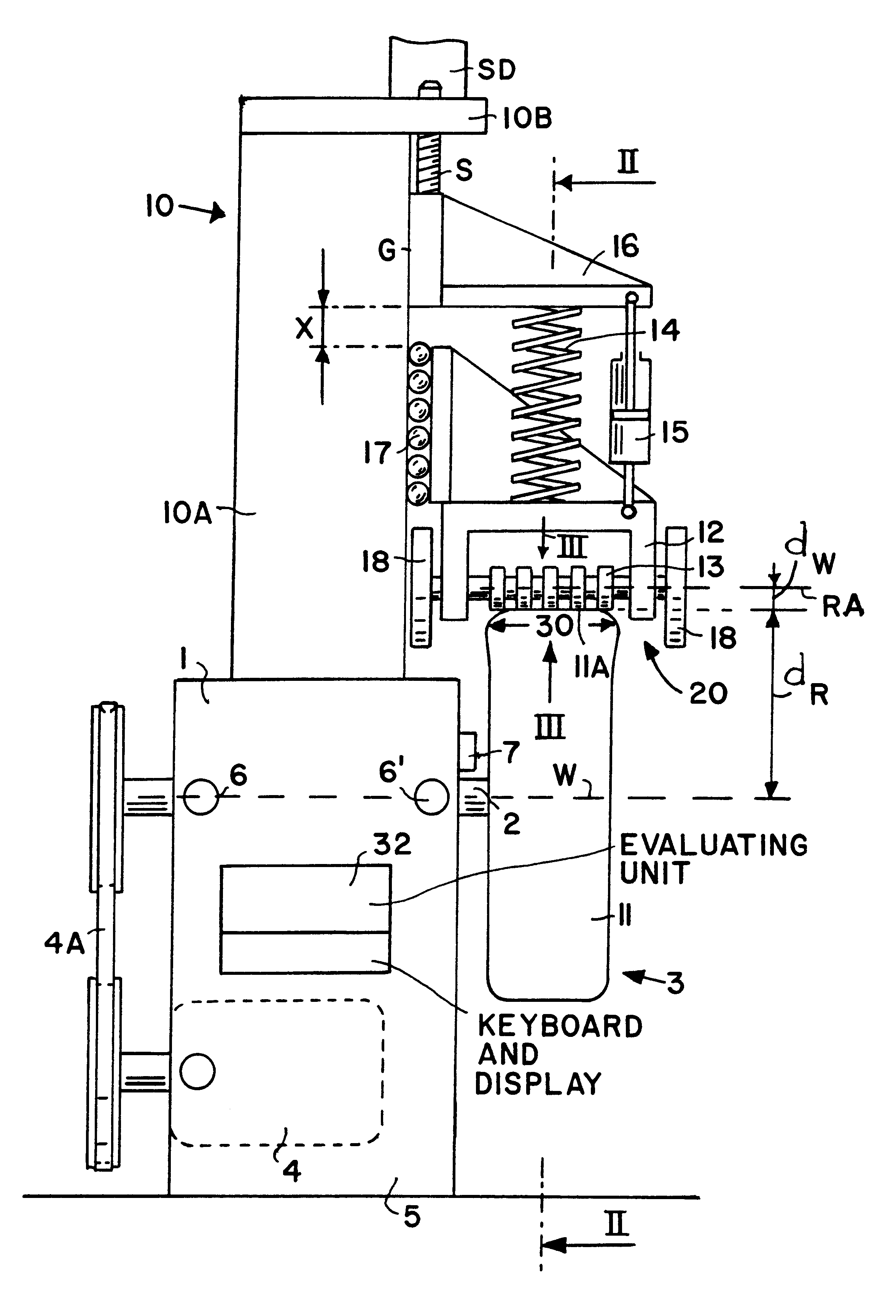
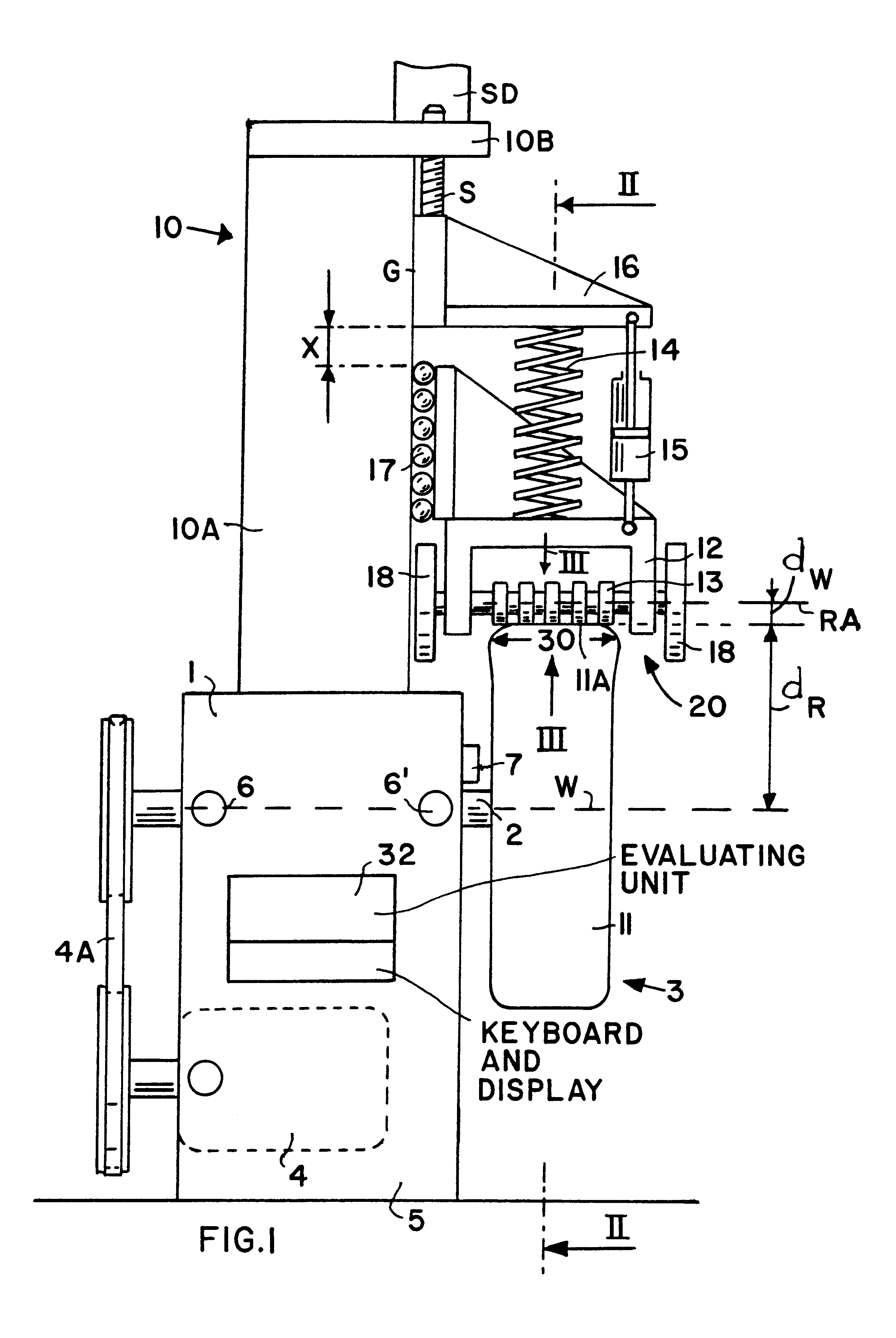
FIG. 1 shows an apparatus for simulating loads that optimally resemble actual vehicle operating conditions for reducing vibrations caused by a wheel unit. The apparatus comprises a measuring unit or so-called balancing machine 1 for determining vibrations of a wheel unit 3. The measuring unit 1 comprises a rotatable balancing spindle 2 conventionally mounted on two oscillating bridges not shown. The oscillating bridges are supported on spring elements mounted in a machine frame 5. A drive motor 4 is used for rotating the balancing spindle 2, for example, by means of a belt drive 4A. The wheel unit 3 is mounted on the balancing spindle 2 for rotation with the spindle 2. As the wheel unit 3 rotates, the balancing spindle 2 oscillates and respective vibrations are transmitted by the balancing spindle 2 to the oscillating bridges. Sensors 6, 6' are arranged in the measuring unit 1 to detect vibrations of the two oscillating bridges relative to a horizontal plane extending through a spin...


PUM


Abstract

Vibrations generated by the wheel units of a vehicle are reduced by a low pulsating operation that optimally simulates actual vehicle operating conditions. For this purpose the mass moment of inertia of the wheel unit and of rotating components such as the hub and the brake disc are taken into account. The wheel unit is rotatably mounted on a balancing spindle (2) in a measuring apparatus to determine the mass and angular location of balancing weights (31). The vibrations are measured at a speed that corresponds to a typical travel speed of a vehicle. A loading mechanism including a roller shoe (20) applies a force to the tire tread surface through a spring damping (14, 15) to optimally simulate the conditions of a roadway. The roller shoe (20) has rollers (13) with sections of larger and smaller diameters so that neighboring rollers intermesh. The combined masses of the rollers, as reduced to the roller radius dw, corresponds to the rotational mass of the vehicle wheel as reduced to the tread radius (dR). It is also possible to disengage the contact force from the tread surface for dynamically balancing the wheel unit under load-free conditions. Thus, wheel-balancing steps under loaded and load free conditions can be done on one machine.

Description

PRIORITY CLAIMThis application is based on and claims the priority under 35 U.S.C. .sctn.119 of German Patent Application 199 09 162.5, filed on Mar. 3, 1999, the entire disclosure of which is incorporated herein by reference.The invention relates to a method for reducing vibrations transmitted by a wheel unit to a vehicle to which the wheel unit is mounted. The invention further relates to an apparatus for reducing such vibrations.BACKGROUND INFORMATIONThe wheel units of a vehicle are guided by guide arms and support the sprung mass of the vehicle by means of spring or damping devices. The term "wheel unit" as used here refers to a tire mounted on a wheel rim. Irregularities in a tire, such as localized variations in the tire elasticity, dimensional deviations, unbalances and other irregularities in the wheel rim and / or tire characteristics of the wheel unit can cause undesirable vibrations that are transmitted to other components of the vehicle. Vibrations that are transmitted to ...

Claims


Application Information

Patent Timeline
IPC IPC(8): G01M1/00G01M17/02G01M1/30
CPCG01M17/022G01M1/30
Inventor SCHOENFELD, HARALD
Owner SCHENCK ROTEC GMBH
Why Eureka
Try Eureka