
Smooth-table circular needling machine

a needling machine and smooth table technology, applied in the field of circular needling machines, can solve the problems of inability to know the exact position of the top surface of the preform, the brush (or felt) is produced in a large amount, and the configuration of the circular machine with a brush (or felt) platen presents numerous drawbacks

Inactive Publication Date: 2002-04-09
SAFRAN LANDING SYSTEMS
View PDF8 Cites 36 Cited by
  • Summary
  • Abstract
  • Description
  • Claims
  • Application Information

AI Technical Summary

Benefits of technology

This revolutionary structure for a circular needling machine using a platen or table that is "smooth" makes it possible to provide annular preforms presenting needling density that is uniform throughout the thickness of the preform and in which the various layers are of constant thickness.

Problems solved by technology

That circular machine configuration with a brush (or felt) platen unfortunately presents numerous drawbacks.
Firstly the difficulty in securing the first layers of the preform generally makes it necessary to perform over-needling on them, which not only modifies needling density in the preform in said first layers, but also raises a problem when the preform is to be removed, since it must then be torn away from the brush or taken away together with the felt.
Further, when the fibers for needling are of a brittle type such as carbon fibers, a particularly large amount of pollution is produced in the brush, which must be cleaned frequently in order to avoid the machine becoming dirtied to an extent that is harmful to making preforms.
Finally, the flexibility provided by the presence of a brush or a belt, whereby the brush or felt is compressed to an increasing extent with increasing thickness of the preform, means that it is not possible to know the exact position of the top surface of the preform, and thus that it is not possible to have full control over needle penetration.

Method used


Image

  • Smooth-table circular needling machine
  • Smooth-table circular needling machine
  • Smooth-table circular needling machine

Examples


Embodiment Construction

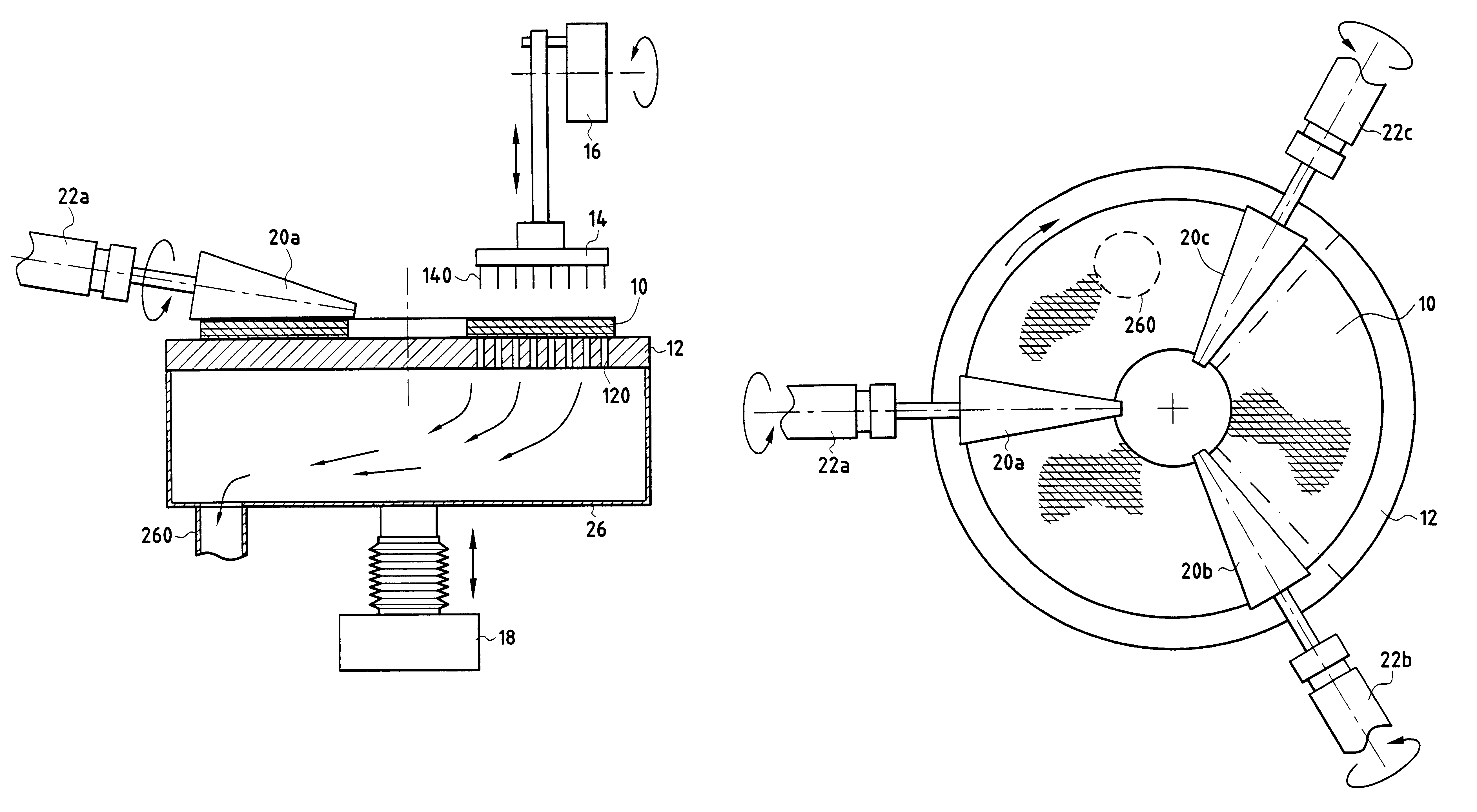
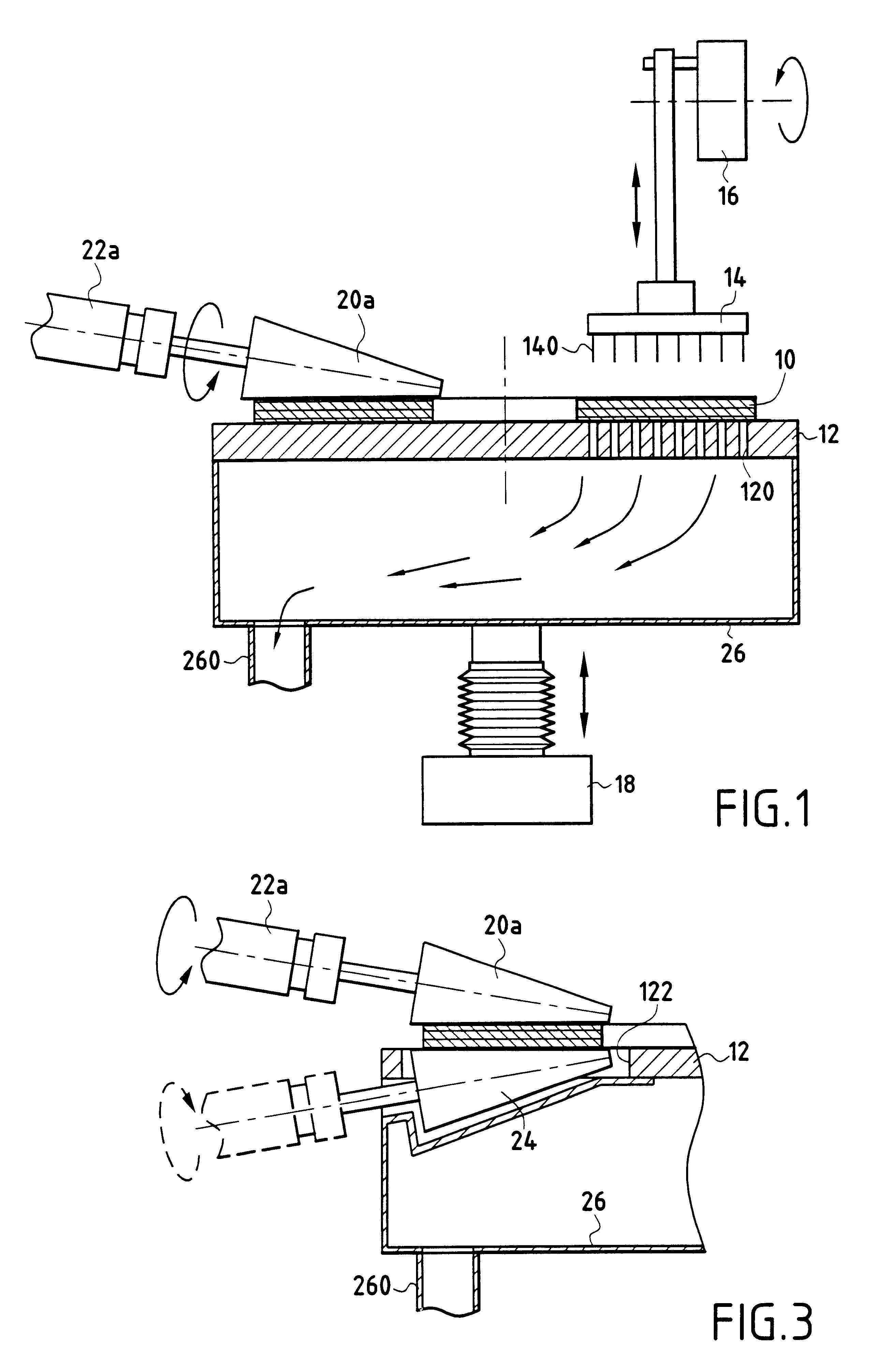
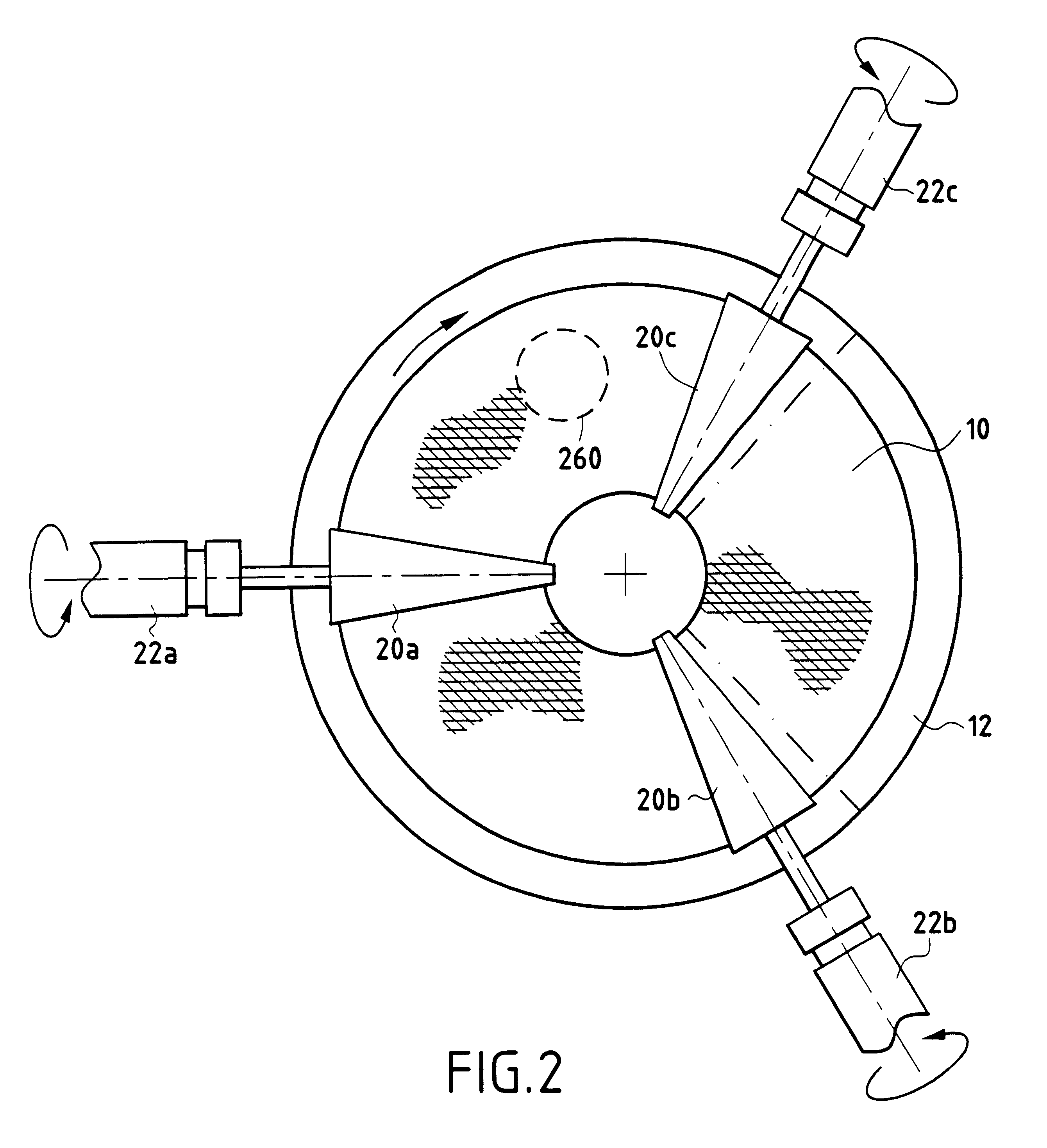
A circular needling machine of the invention is shown in FIG. 1 in highly diagrammatic manner.

Conventionally, in a circular needling process, annular textile layers or plies are stacked and needled together on a platen to form a needled fiber preform of annular shape. The plies can be previously formed as rings or juxtaposed ring sectors cut out from a woven or non-woven fabric of unidirectional or multidirectional fibers. They can also be formed by winding turns flat from a feeder device of the kind described in the patent application filed on the same day as the present application, assigned to the same Assignee, and entitled "Feeding a needling machine with a continuous spiral strip", or turns formed from deformed braid, or indeed turns formed from a deformable two-dimensional fabric.

The annular preform 10 which can in particular constitute a preform for a brake disk of composite material, rests directly on a platen 12 forming a needling table. It is rotated and passes through a ...


PUM

PropertyMeasurementUnit
anti-frictionaaaaaaaaaa
densityaaaaaaaaaa
brittleaaaaaaaaaa

Abstract

In a circular needling machine for needling an annular preform and comprising both a vertically movable needling table serving as a horizontal support for said annular preform, and a needling head having a determined number of barbed needles disposed over the needling table in a needling zone and driven with vertical reciprocating motion, provision is made for the annular preform to be placed directly on the needling table and for it to be driven in rotation on the needling table by drive means while the needling table remains rotationally stationary during said rotation. The drive means comprise a set of conical friction rollers kept continuously in contact with the annular preform.

Description

The present invention relates to the field of needled textile structures and it relates more particularly to a needling machine of the circular type.PRIOR ARTCircular type needling machines are now well known, as shown for example by patent applications FR 2 626 294 or EP 0 849 389. In those conventional machines, the textile structure is needled by relative angular rotation between a horizontal platen supporting the structure and a needling head performing vertical reciprocating motion. In general, because of the reciprocating motion of the head, it is the support platen which rotates and it is the needling head which does not rotate. Furthermore, in order to keep the preform on the platen during rotation and in order to guarantee that it is properly held down, the platen is covered in a material that allows needling to take place, such as a succession of polypropylene fiber felts interconnected by adhesive or stitching (see for example application EP 0 232 059) or a set of brush m...

Claims


Application Information

Patent Timeline
Patent Type & Authority Patents(United States)
IPC IPC(8): D04H18/00D04H1/48D04H18/02D04H1/70
CPCD04H18/02D04H18/00D04H1/48D04H1/70
Inventor DUVAL, RENAUDMARJOLLET, THIERRYJEAN, ROBERT
Owner SAFRAN LANDING SYSTEMS
Features
  • Generate Ideas
  • Intellectual Property
  • Life Sciences
  • Materials
  • Tech Scout
  • Unparalleled Data Quality
  • Higher Quality Content
  • 60% Fewer Hallucinations
Learn More