
Oil injection lubrication system for two-cycle engines

a lubrication system and two-cycle technology, applied in the direction of lubrication for crankcase compression engines, machines/engines, combustion engines, etc., can solve the problems of more lubrication, variations in the appropriate amount of oil required, and conventional systems that do not provide the capability of adjusting the amount of oil delivered

Inactive Publication Date: 2002-04-23
SANSHIN KOGYO CO LTD
View PDF20 Cites 15 Cited by
  • Summary
  • Abstract
  • Description
  • Claims
  • Application Information

AI Technical Summary

Benefits of technology

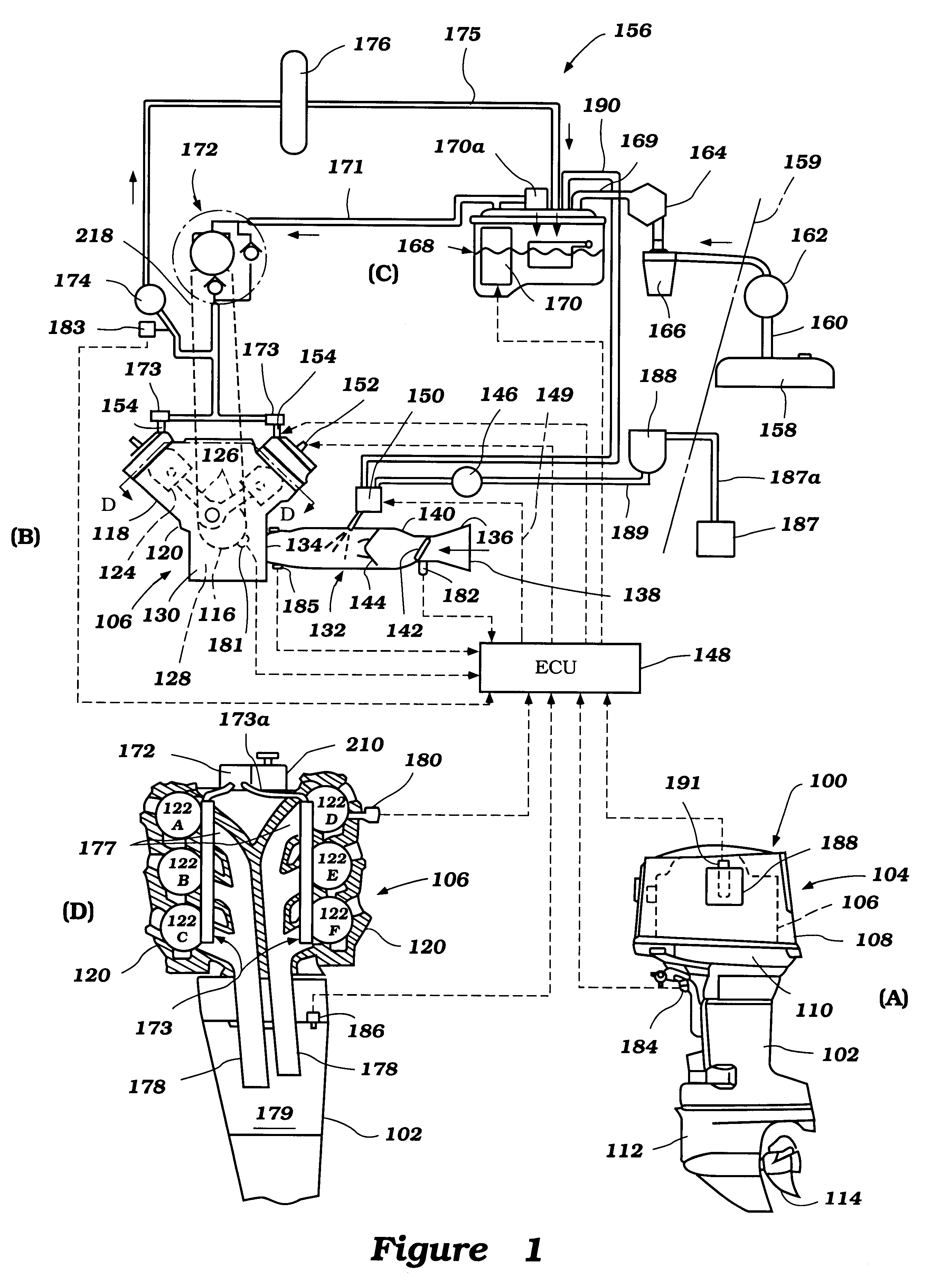
In one mode, an oil supply pipe carries a flow of oil from the valve unit to a vapor separator tank for mixture with the fuel supply in order to reduce the formation of deposits on fuel injectors, lubricate the fuel system, and / or prevent corrosion.
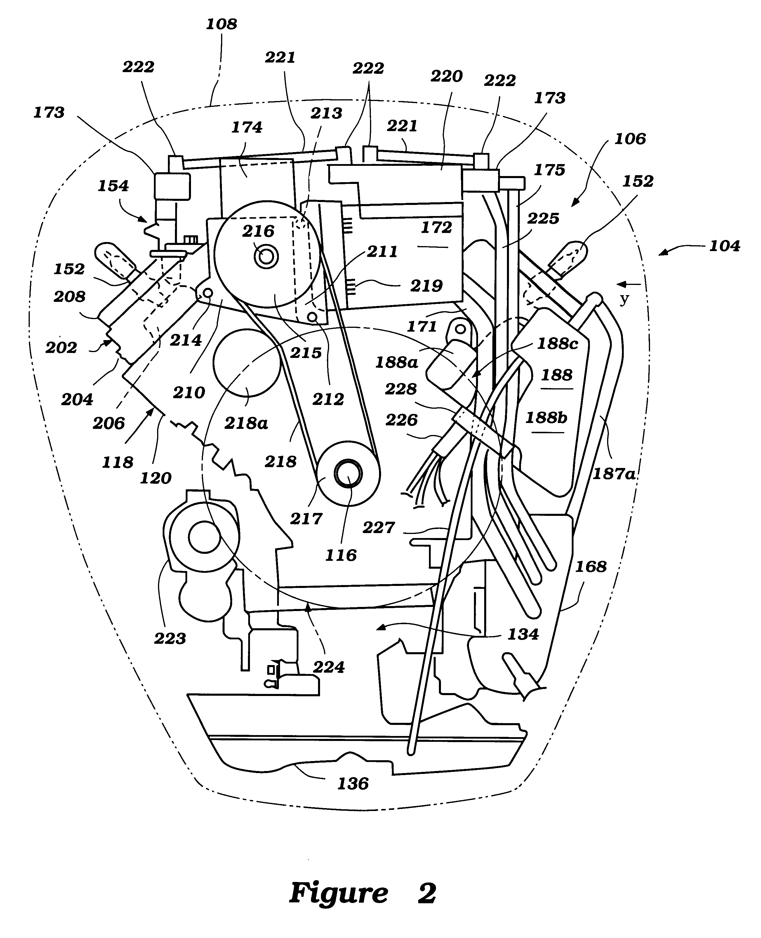
In accordance with another aspect of the present invention, the lubrication system comprises an oil tank having a recess and a number of raised portions that allow the tank to be mounted to the engine in a compact configuration proximate the flywheel without interference while providing a passageway for control lines and fluid conduits in the recess. The oil tank is also preferably configured to have an inlet that remains above the maximum oil level to prevent backflow or siphoning of oil back into a supply tank in the hull of a watercraft.

Problems solved by technology

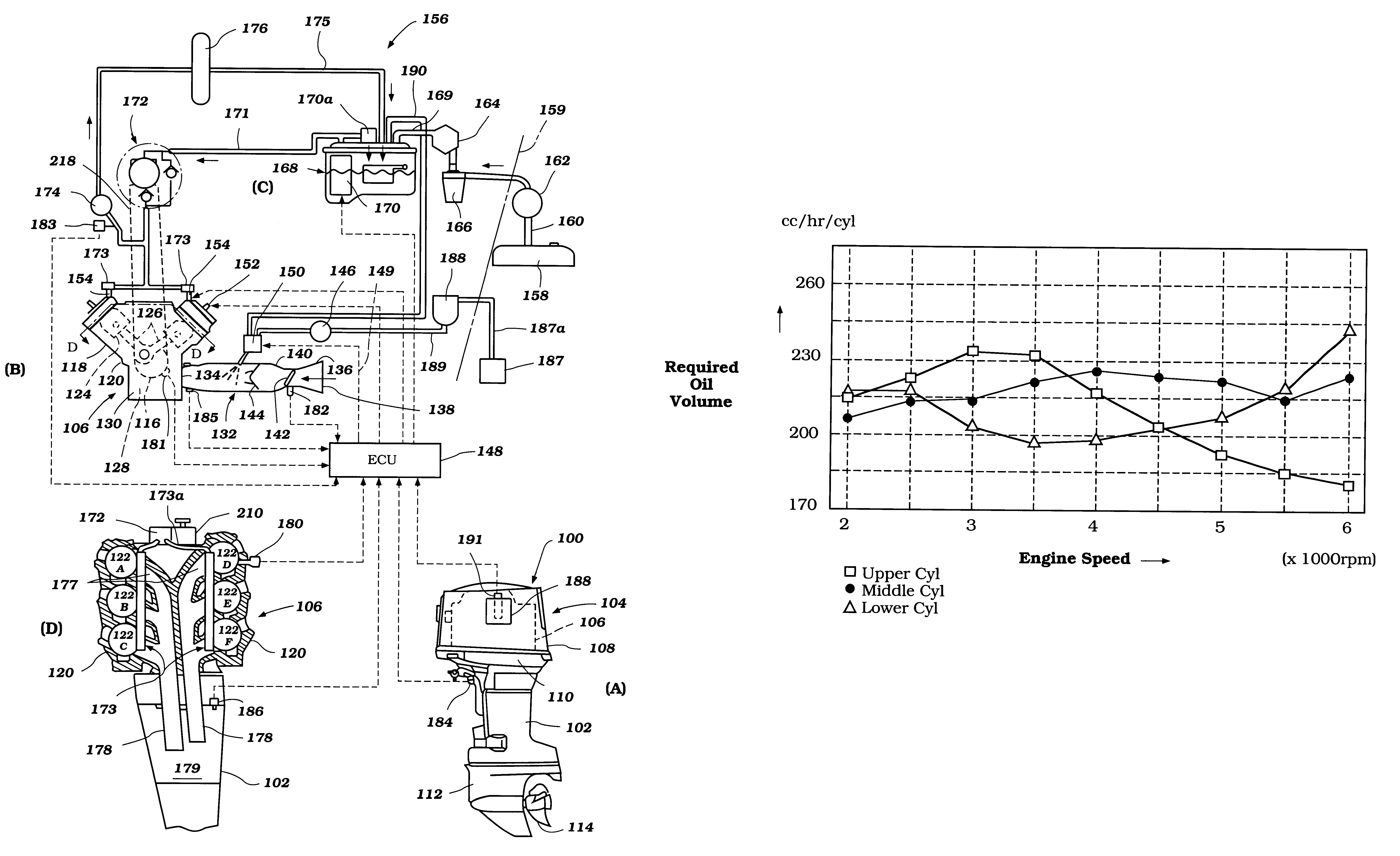
Under certain conditions, however, some cylinders of some engines require more lubricating oil than other cylinders.
Furthermore, operating conditions such as cylinder resting periods, idling periods, rapid acceleration periods, or continuous speed periods often result in variations in the appropriate amount of oil required for each cylinder.
Conventional systems do not provide the capability of adjusting the amount of oil delivered to each cylinder to compensate for these situations.
Consequently, conventional systems suffer from problems such as smoke generated by the mixture of air and lube oil, odor, and heavy oil consumption.
Consequently these systems adversely draw a relatively large amount of electrical power during low engine speed periods when it is also more difficult to generate electrical power.
Still another disadvantage of existing systems is that they would require a complicated layout of solenoid valves and lines in order to be adapted to multiple cylinder engines.
Further, particularly for direct fuel injection type engines, fuel pipes and wires may have to detour around the oil tank, resulting in undesirably long pipes and wires.
Longer pipes and wires are less efficient and more susceptible to damage.
Prior art oil tanks are also susceptible to backflow or siphoning of the lubricating oil back into a main tank located in the hull of the boat, when, for example, the oil tank is tilted as the engine is raised out of the water.

Method used


Image

  • Oil injection lubrication system for two-cycle engines
  • Oil injection lubrication system for two-cycle engines
  • Oil injection lubrication system for two-cycle engines

Examples


Embodiment Construction

In the following description, reference is made to the accompanying drawings, which form a part of this written description of the invention, and which show, by way of illustration, specific embodiments in which the invention can be practiced. It is to be understood that other embodiments may be utilized and structural changes may be made without departing from the scope of the present invention. Where possible, the same reference numbers will be used throughout the drawings to refer to the same or like components. Numerous specific details are set forth in order to provide a thorough understanding of the present invention. However, it will be obvious to one skilled in the art that the present invention may be practiced without the specific details or with certain alternative equivalent devices and methods to those described herein. In other instances, well-known methods, procedures, components, and devices have not been described in detail so as not to unnecessarily obscure aspects...


PUM


Abstract

The invention provides an improved oil injection lubrication system for two-cycle engines. The system includes a variable output oil pump, the output of which can be varied in relation to the throttle level. The system also includes a solenoid valve unit containing a plurality of solenoid valves that further regulates the flow of oil from the oil pump to each cylinder. An electronic control unit sends control signals to the soleniod valve unit to regulate the flow of oil based upon engine operating conditions in accordance with a controle scheme. The combination of the variable output oil pump and the solenoid valve unit enables the solenoid valves to be activated with a lighter duty cycle, which reduces the amount of power consumed by the solenoid valve unit.

Description

1. Field of the InventionThe present invention relates to oil injection lubrication systems for engines, and more particularly to an oil injection system for lubricating a multiple cylinder engine.2. Description of the Related ArtFor two-cycle engines, it is a common practice to mix lubricating oil with induction air to lubricate engine parts. Conventional systems typically mix oil with induction air in the same proportion regardless of engine speed. Such systems also typically deliver the same amount of oil to each cylinder regardless of the engine operating conditions. Under certain conditions, however, some cylinders of some engines require more lubricating oil than other cylinders. Furthermore, operating conditions such as cylinder resting periods, idling periods, rapid acceleration periods, or continuous speed periods often result in variations in the appropriate amount of oil required for each cylinder. Conventional systems do not provide the capability of adjusting the amount...

Claims


Application Information

Patent Timeline
IPC IPC(8): F01M3/02F01M1/16F01M3/00F02B75/02
CPCF01M1/16F01M3/02F02B2075/025
Inventor KATO, MASAHIKO
Owner SANSHIN KOGYO CO LTD
Learn More