
Electro-polishing fixture and electrolyte solution for polishing stents and method

a technology of electrolyte solution and electrolyte solution, which is applied in the direction of prosthesis, manufacturing tools, blood vessels, etc., can solve the problems of coarse surface finish unsuitable for living tissue implantation, ineffective uniform polishing of tubular stent interior and exterior surfaces, and simple immersion in electrolyte baths. achieve the effect of high degree of uniformity in polishing

Inactive Publication Date: 2002-04-23
ABBOTT CARDIOVASCULAR
View PDF4 Cites 254 Cited by
  • Summary
  • Abstract
  • Description
  • Claims
  • Application Information

AI Technical Summary

Benefits of technology

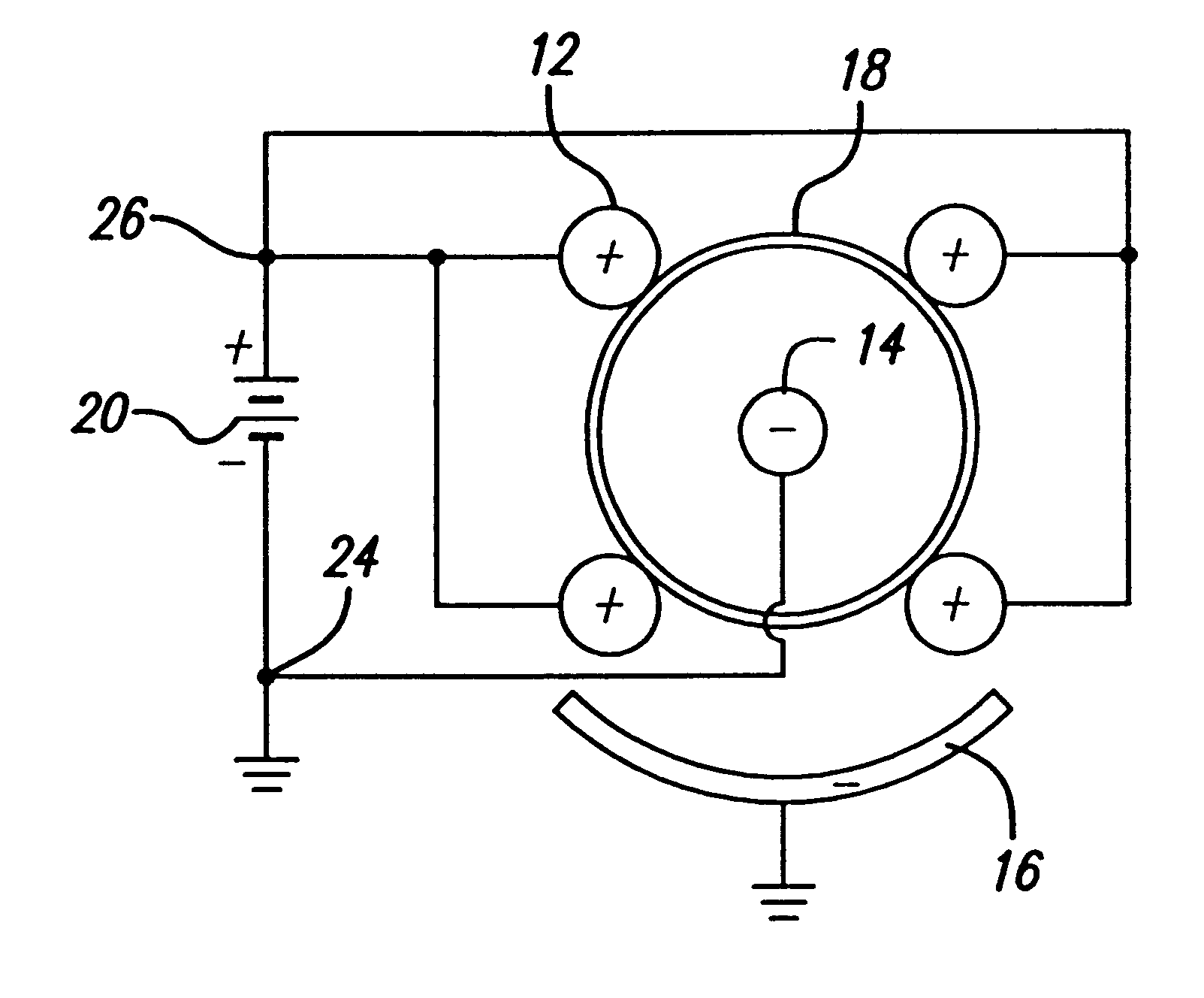
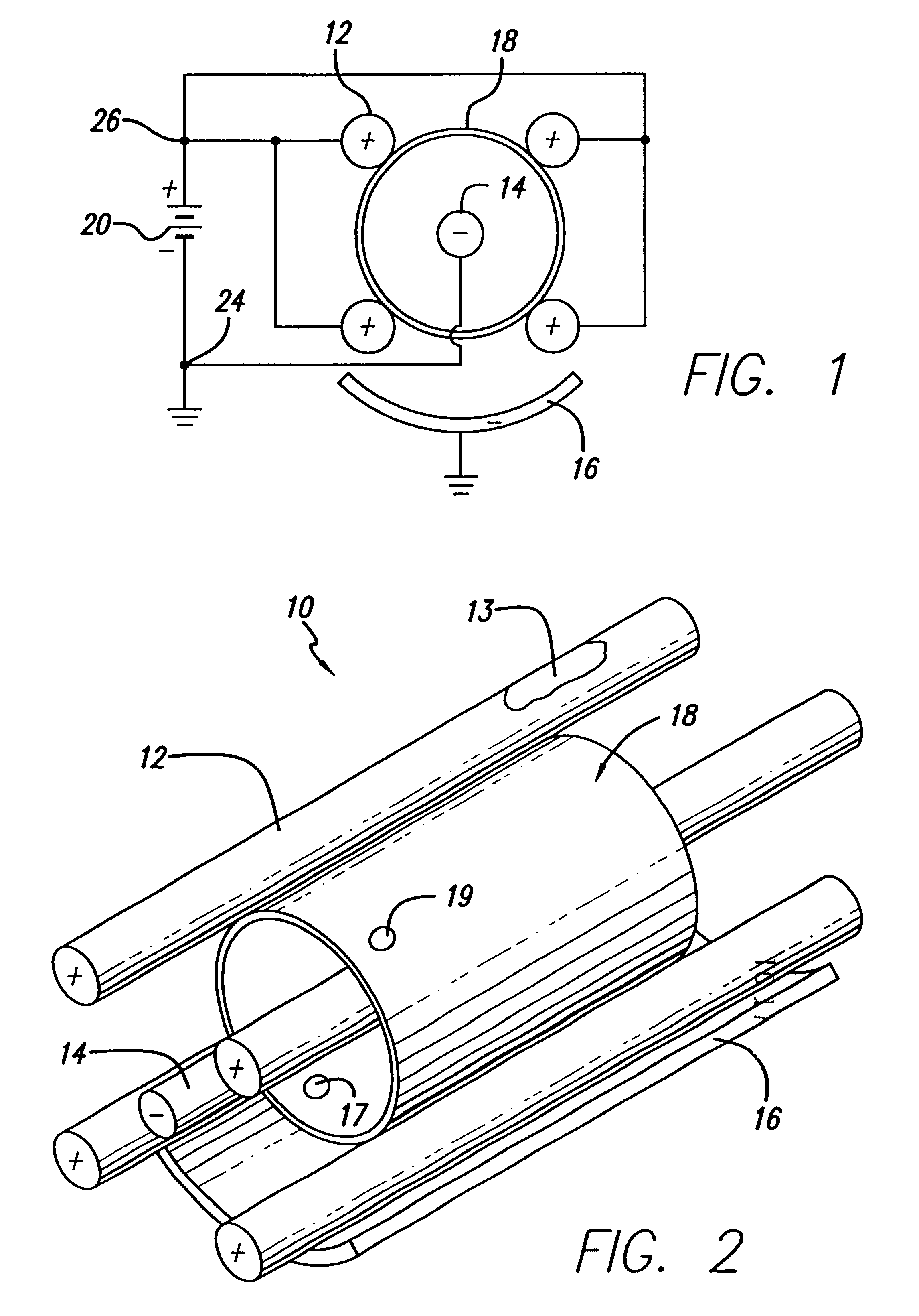
The present invention provides an electro-polishing fixture for providing a fine uniform polish on both the interior and exterior surfaces of metallic stents. The fixture achieves this result by providing a plurality of anodes around the circumference of a stent thereby creating uniform current density in the surrounding electrolyte when the stent is place within an electrolytic bath. The fixture of the present invention further includes a center cathode centrally located within the interior of a stent, which provides for uniform polishing of a stent's interior surface. The invention also includes a curved exterior cathode disposed about the perimeter of the stent which provides for uniform polishing of a stent's exterior surface. The combination of dual interior and exterior cathodes in conjunction with a plurality of anodes provides a high degree of uniformity in polishing.

Problems solved by technology

Either machining process leaves a thin heat effected zone around the pattern cut in the drawn tube and a resulting surface finish that is coarse and unsuitable for implantation in living tissue.
The presence of such surface anions leads to deterioration of the newly polished surface when the residual anions come into contact with calcium and magnesium ions which are commonly found in non-deionized water (ordinary tap water).
Although electro-polishing has proven to be an effective method of obtaining extremely smooth surfaces on the order of 0.2 to 0.05 microns surface roughness on relatively flat surfaces, simple immersion in an electrolytic bath has proven ineffective in obtaining a uniform degree of polish on both the interior and exterior surfaces of a tubular stent.
In addition, electrolyte solutions specifically formulated for use with nickel-titanium alloys are needed as typical solutions formulated for use with stainless steel, generally have not been able to achieve the desired surface finish.

Method used


Image

  • Electro-polishing fixture and electrolyte solution for polishing stents and method
  • Electro-polishing fixture and electrolyte solution for polishing stents and method
  • Electro-polishing fixture and electrolyte solution for polishing stents and method

Examples


example

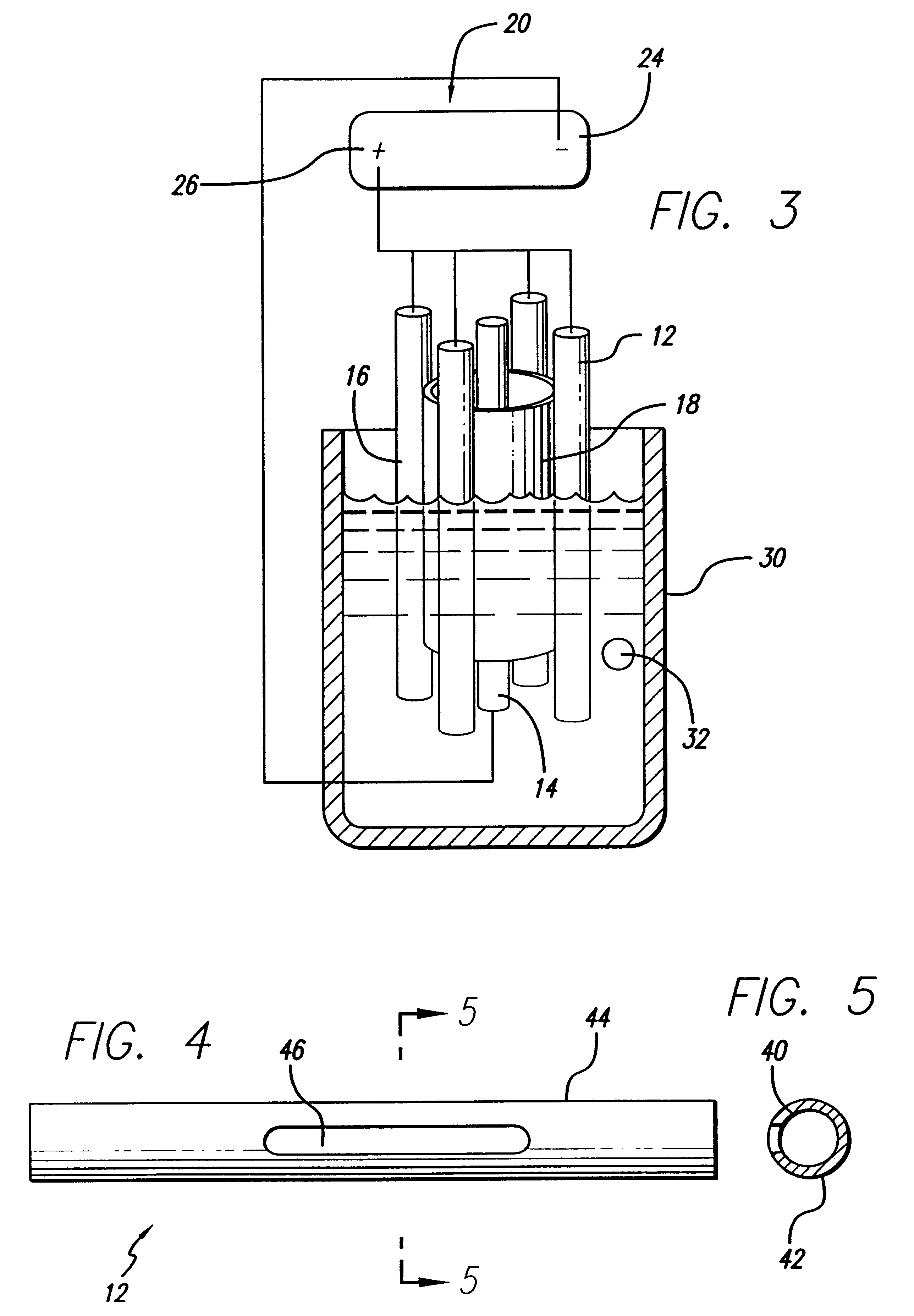
With reference to FIG. 3, the following is a detailed example of polishing a nickel-titanium stent using the electro-polishing fixture and electrolyte of the present invention. A nickel-titanium stent of 8 mm diameter, with a length of 20 mm, with a wall thickness of 0.15 mm and a resistence of 9 ohms was descaled by bead blasting and then placed over the center cathode 14 and within the holding anodes 12 of the polishing fixture 10 of the present invention. Four anodes 12 proved sufficient to maintain a uniform current density between the stent and the cathodes 14 and 16. In order to provide a preferred path for current flow, the anodes 12 possessed a resistence of 0.006 ohms. In order to achieve the desired degree of polishing on the outside of the stent, the curved exterior cathode 16 was radially spaced at 6 mm from the stent exterior surface. The electro-polishing was conducted in about 500 ml of electrolyte 32 which comprised a solution of about 465 ml of absolution methanol, ...


PUM

PropertyMeasurementUnit
surface roughnessaaaaaaaaaa
temperatureaaaaaaaaaa
surface roughnessaaaaaaaaaa

Abstract

An electro-polishing fixture for polishing stents which incorporates multiple anodes in contact with the stent and a center cathode disposed coaxially within the interior of the stent and a curved exterior cathode disposed about the perimeter of the stent. The invention further includes an electrolyte solution adapted for polishing stents composed of nickel-titanium alloy and a method of using the electrolyte in combination with the electro-polishing fixture.

Description

BACKGROUND OF THE INVENTIONThe present invention is directed to the field of electro-polishing metallic stents, with particular application to stents manufactured from nickel-titanium and stainless steel alloys.Stents are used in conjunction with a medical procedure known as balloon angioplasty which is used to restore blood flow through obstructed or partially obstructed arteries. In an angioplasty procedure, a balloon catheter is inserted into an artery and advanced to the site of an arterial lesion. Subsequently, the catheter balloon is inflated to expand the artery and compress the accumulated atherosclerotic plaque which forms the arterial lesion against the artery wall, thereby restoring blood flow through the vessel. In a certain percentage of cases, the expanded artery will collapse after deflation of the catheter balloon or will slowly narrow over a period of time. To solve this problem, intravascular prostheses commonly referred to as stents have been developed.A stent gen...

Claims


Application Information

Patent Timeline
Patent Type & Authority Patents(United States)
IPC IPC(8): C25F7/00A61F2/06A61F2/90A61F2/84C25F3/16C25F3/22
CPCC25F7/00A61F2/91
Inventor WANG, JINGLITARAPATA, CHRISTOPHER J.FITZ, MATTHEW J.
Owner ABBOTT CARDIOVASCULAR
Learn More