Method for producing silicon ingot having directional solidification structure and apparatus for producing the same

a technology of solidification structure and silicon ingot, which is applied in the direction of glass pressing apparatus, crystal growth process, glass tempering apparatus, etc., can solve the problems of poor vertical orientation along the solidification direction, inability to effectively utilize the expensive silicon raw material, and inability to obtain silicon ingots with a suitable degree of orientation

Inactive Publication Date: 2002-04-30
MITSUBISHI MATERIALS CORP
View PDF13 Cites 35 Cited by
  • Summary
  • Abstract
  • Description
  • Claims
  • Application Information

AI Technical Summary

Problems solved by technology

However, when the silicon ingot obtained has a small horizontal cross-sectional area, the horizontal cross-sectional area of the silicon ingot after shaving off the side wall part becomes still smaller along with increasing the silicon ingot side wall elimination ratio, making it impossible to effectively utilize the expensive silicon raw material.
However, when one attempts to produce a silicon ingot having a wide horizontal cross-sectional area by the conventional production method in which the temperature is controlled by disposing heat generation sources on side faces, the degree of orientation along the vertical (i.e., solidification) direction becomes poor due to temperature differences caused along the horizontal direction, making it impossible to obtain a silicon ingot having a suitable degree of orientation.
A large quantity of SiC remains especially when a thick silicon ingot is produced because molten state of silicon is required to be kept for a long period of time.
Only a part of the inert gas used for chilling the chill plate is recycled because, when the feed volume of the inert gas is too large, the gas can not be kept at a high temperature.

Method used


Image

  • Method for producing silicon ingot having directional solidification structure and apparatus for producing the same
  • Method for producing silicon ingot having directional solidification structure and apparatus for producing the same
  • Method for producing silicon ingot having directional solidification structure and apparatus for producing the same

Examples


example 1

Conventional Example 1

The silica crucible with a depth of 300 mm, an inner diameter of 400 mm and an outer diameter of 450 mm was mounted on a chill plate 7 shown in FIG. 5(b). A large horizontal cross-sectional area silicon ingot having a directional polycrystalline solidification structure with the same thickness of 200 mm and outer diameter of 400 mm as in Example 1 was produced by the steps comprising: melting the silicon raw material in a conventional silica crucible 1 shown in FIG. 5(a); pouring the molten silicon obtained into the tray-shaped silica crucible as described above; descending the tray-shaped silica crucible filled with the molten silicon at a speed synchronizing with the crystal growth speed of the molten silicon using an elevator shaft 11 together with the chill plate 7; and allowing a directional solidification structure 12 to grow over the entire region of the molten silicon. The degree of orientation of this large horizontal cross-sectional area silicon ingot...

example 2

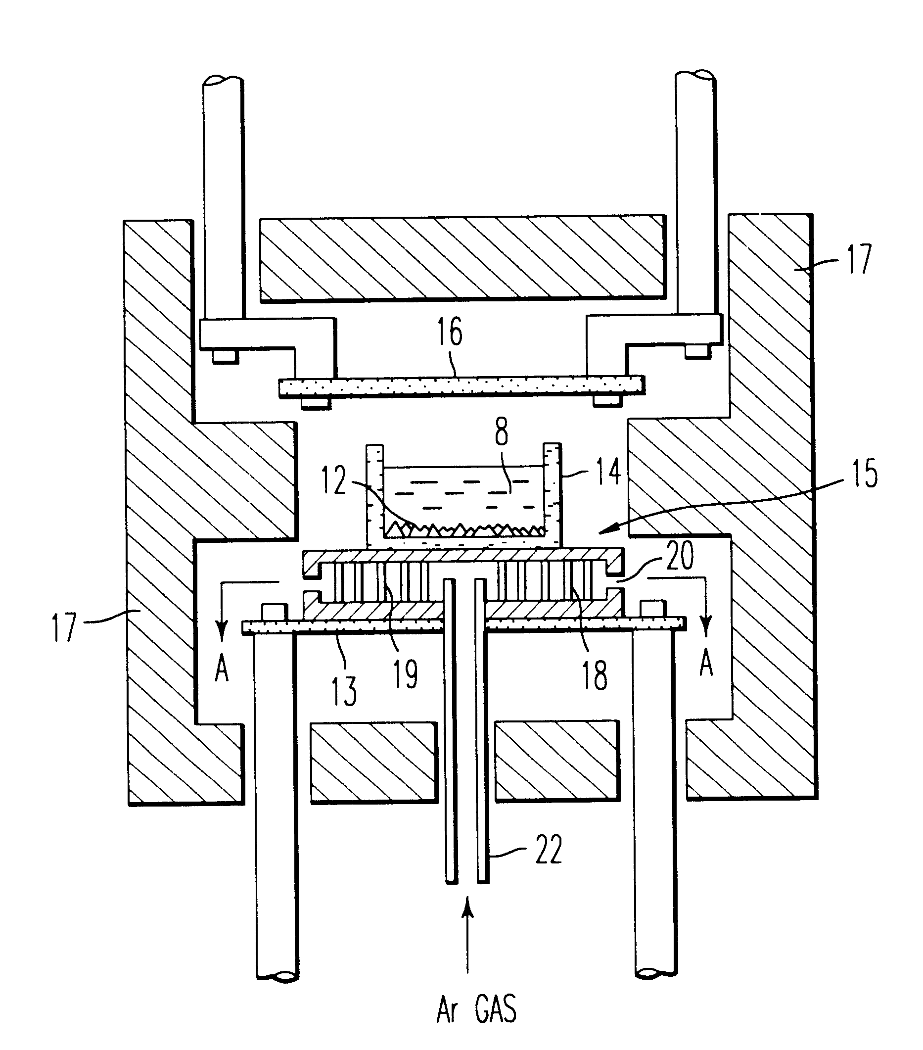
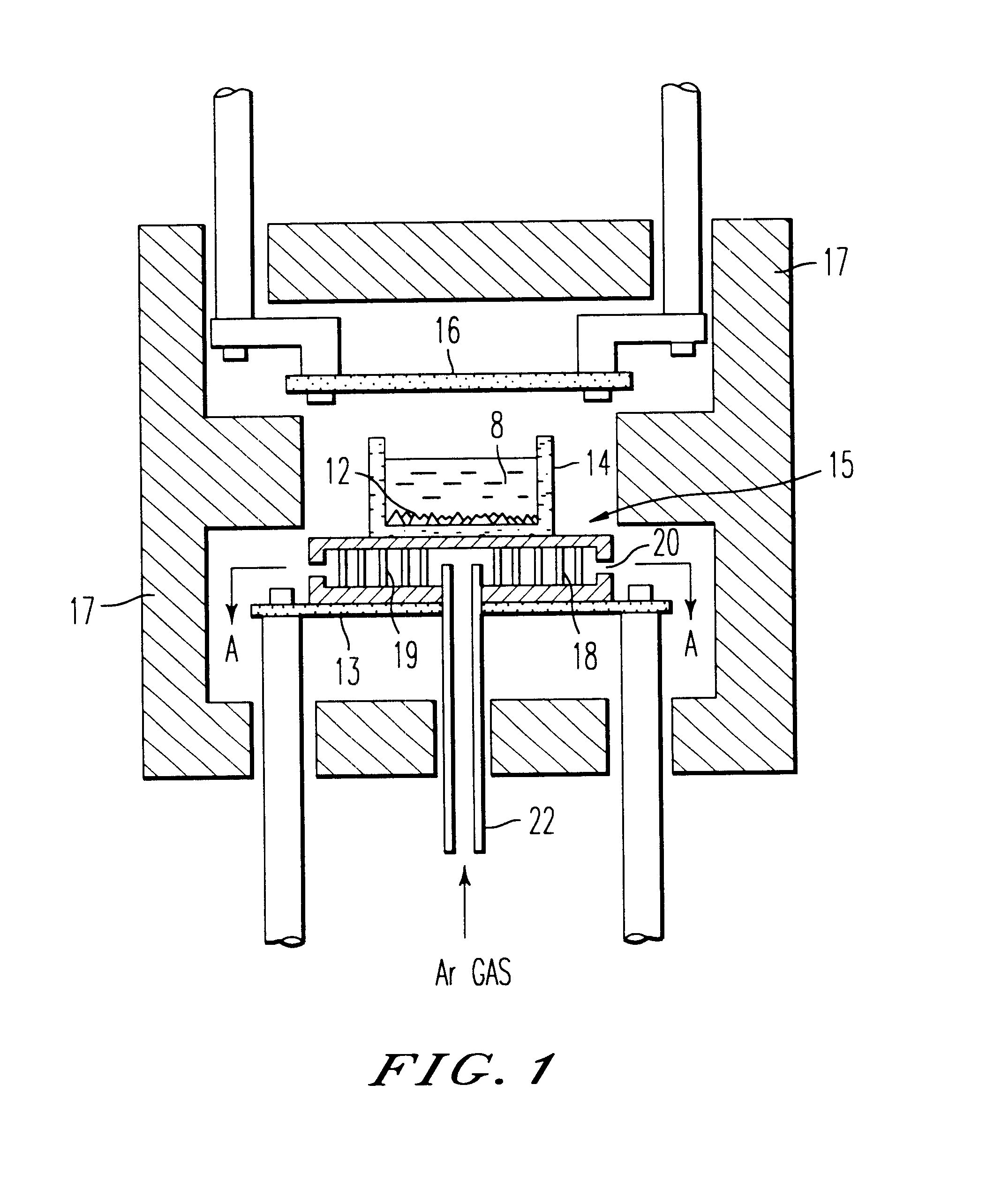
As shown in FIG. 3, a wide horizontal cross-sectional area silicon ingot having a directional solidification structure with an inner diameter of 200 mm and outer diameter of 400 mm was produced by the steps comprising: heating the Ar gas fed from an inert gas feed device 23 at a temperature of 1500.degree. C. with an inert gas pre-heating device 23; completely melting the silicon raw material by flowing an electric current through an underfloor heater 13 and overhead heater 16 while continuously feeding the heated Ar gas into the crucible; halting the electric current of the underfloor heater 13 followed by flowing the Ar gas to the chill plate 15 having a hollow part 18 to chill the molten silicon from the bottom of the crucible; and continuously lowering the temperature of the overhead heater 16 by continuously reducing the electric power through the overhead heater 16.

The degree of orientation of this wide horizontal cross-sectional area silicon ingot having a directional polycry...

example 3

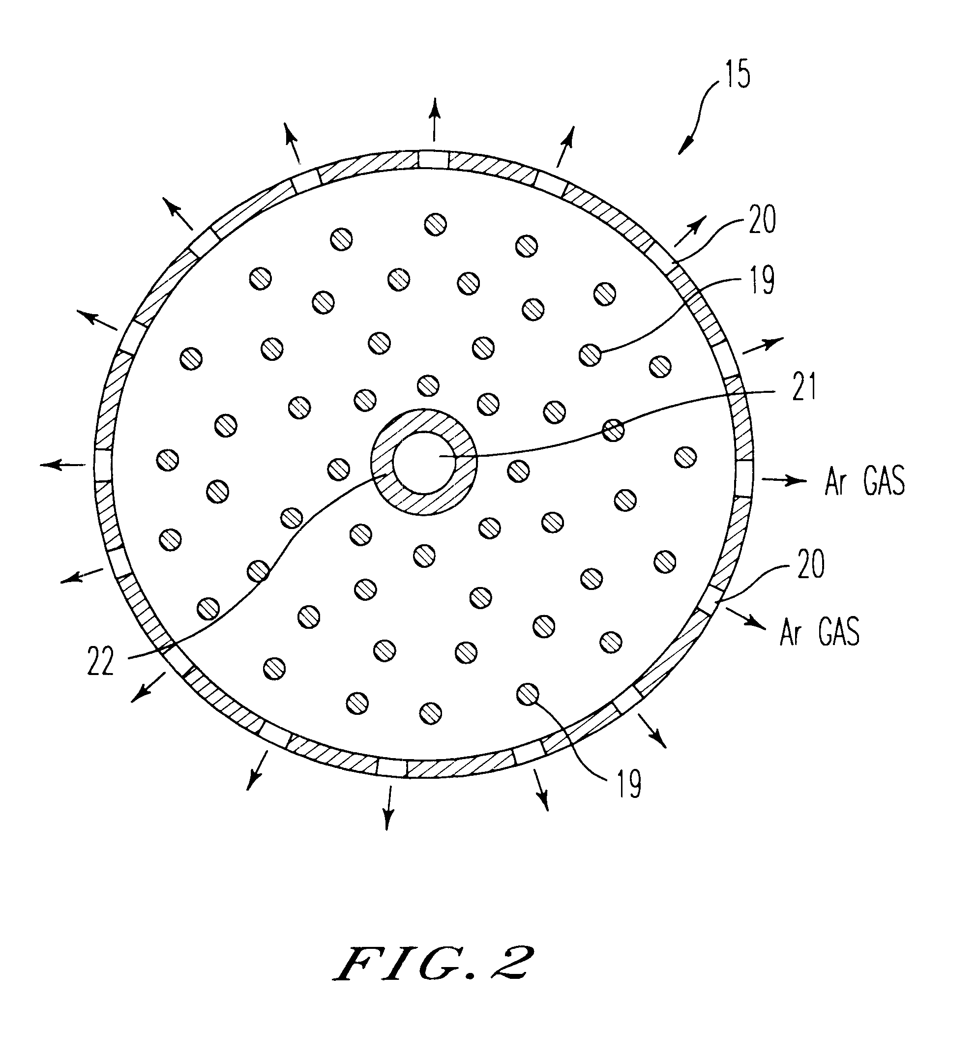
A molten silicon 8 was produced by completely melting the silicon raw material by flowing an electric current through an underfloor heater 13 and overhead heater 16 as shown in FIG. 4. The electric current through the underfloor heater 13 was halted followed by chilling the bottom of the silica crucible by flowing the Ar gas through a chill plate 15 having a hollow part 18 to chill the molten silicon from the bottom of the crucible. The temperature of an overhead heater 16 was continuously lowered by continuously reducing the electric current through the overhead heater 16. An amount of the Ar gas as small as not to chill the chill plate was fed from a feed pipe 22 and the gas was discharged from a refrigerant exit 20 through the hollow part 18 of the chill plate 15. An Ar gas atmosphere was maintained in the crucible by feeding the Ar gas into the crucible while heating the gas at a temperature of 1500.degree. C. with a pre-heating coil 30 by passing through the gas passage 29. A s...


PUM

PropertyMeasurementUnit
temperatureaaaaaaaaaa
outer diameteraaaaaaaaaa

Abstract

A method for producing a silicon ingot having a directional solidification structure comprising the steps of: placing a silicon raw material into a crucible of a melting device constructed by mounting a chill plate on an underfloor heater, mounting a crucible with a large cross-sectional area on the chill plate, providing an overhead heater over the crucible, and surrounding the circumference of the crucible with a heat insulator; heat-melting the silicon raw material by flowing an electric current through the underfloor heater and overhead heater; chilling the bottom of the crucible by halting the electric current through the underfloor heater after the silicon raw material has been completely melted to form a molten silicon; chilling the bottom of the crucible by flowing an inert gas through the chill plate; and intermittently or continuously lowering the temperature of the overhead heater by intermittently or continuously decreasing the electric current through the overhead heater, and an apparatus for producing the silicon ingot.

Description

1. Field of the InventionThe present invention relates to a method for producing a silicon ingot having a directional solidification structure with a suitable degree of orientation for producing a silicon substrate for use in photovoltaic solar cells, especially to a method for producing a silicon ingot having a directional solidification structure with a wide horizontal cross-sectional area and good degree of orientation.2. Description of the Related ArtSilicon substrates comprising polycrystalline silicon have been known in the art as a kind of silicon substrate for use in photovoltaic solar cells. The silicon substrate comprising the polycrystalline silicon is produced by slicing a silicon ingot having a directional solidification structure. Although the silicon ingot having a directional solidification structure is thought to be cheaper than the single crystal silicon, many researches are under way for satisfying requirements for much cheaper silicon substrates.FIG. 5 denotes an...

Claims


Application Information

Patent Timeline
Patent Type & Authority Patents(United States)
IPC IPC(8): C30B11/00C30B29/06
CPCC30B11/003C30B29/06Y10S164/06
Inventor WAKITA, SABUROMITSUHASHI, AKIRANAKADA, YOSHINOBUSASAKI, JUN-ICHIISHIWARI, YUHJI
Owner MITSUBISHI MATERIALS CORP
Why Eureka
Try Eureka