
Water treatment system

a technology of water treatment system and treatment system, applied in the direction of coastline protection, nuclear engineering, foundation engineering, etc., can solve the problems of not being able to solve the problem of addressing in a variety of ways, affecting the effectiveness of treatment, and being subject to various sources of pollution

Inactive Publication Date: 2002-04-30
ECOLOGIC HLDG (PTY) LTD
View PDF22 Cites 31 Cited by
  • Summary
  • Abstract
  • Description
  • Claims
  • Application Information

AI Technical Summary

Benefits of technology

The containing wall portion may be provided with a spillway to allow excess water flows to be discharged from the system in such a way as to cause minimal damage to the structure. Where the bulk of the wall portion is comprised of a rock or rubble material this may be sealed, in the region of the spillway, with concrete or other suitable structural material which defines a spillway through which floodwaters may pass without severely damaging the impounding or containing wall portion.
An advantage of the system and method of the present invention is simplicity of construction and an expected higher efficiency of pollutant, especially nutrient, removal than encountered in prior art treatment methodology.

Problems solved by technology

Waterways, such as wetlands, rivers, creeks, flood prone areas and so on are subject to various sources of pollution.
Significant among these are rain or stormwater flows which may become contaminated with various contaminants and pollutants which exist in the wider environment.
It has been recognised that stormwater is especially polluting in the early time phase following a storm.
These problems have been addressed in diverse and not totally effective ways in the past.
The cost of equipping all entry points to the drainage system in this way would be extreme.
There are limitations to such processing.
Apart from expense, the methodology suffers the critical constraint that only water collected within a municipal drainage system will be treated.
Run off, however, is a much more diffuse source of waterway contamination than this and it can be estimated that much more run off escapes "formal" treatment than is actually treated.
Furthermore, treatment facilities are likely to become less efficient when surge waterflows are generated following heavy rainfall and storms.
Such blooms are highly deleterious to aquatic environments by destruction of ecosystems and reduction of the social amenity of aquatic resources.
Such processes are made difficult by the requirements of efficient plant growth, namely the requirement to provide a good soil medium in which the plants can grow.
Further, once the system has reached a steady state, nutrient take-up plateaus and nutrient bypassing of the reed beds becomes an issue.
Again cost, available land and labour constraints will hinder this process.
In the case of wetland treatment, more complex arrangements may be necessary as contaminated water may diffuse from the wetland around its periphery subject to local topography.
Land area available for the treatment system may be limited.

Method used


Image

  • Water treatment system
  • Water treatment system
  • Water treatment system

Examples


Embodiment Construction

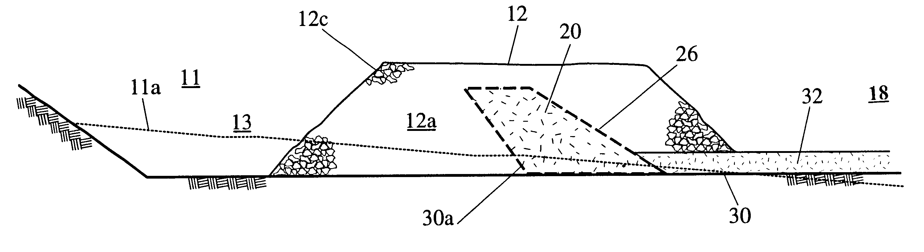
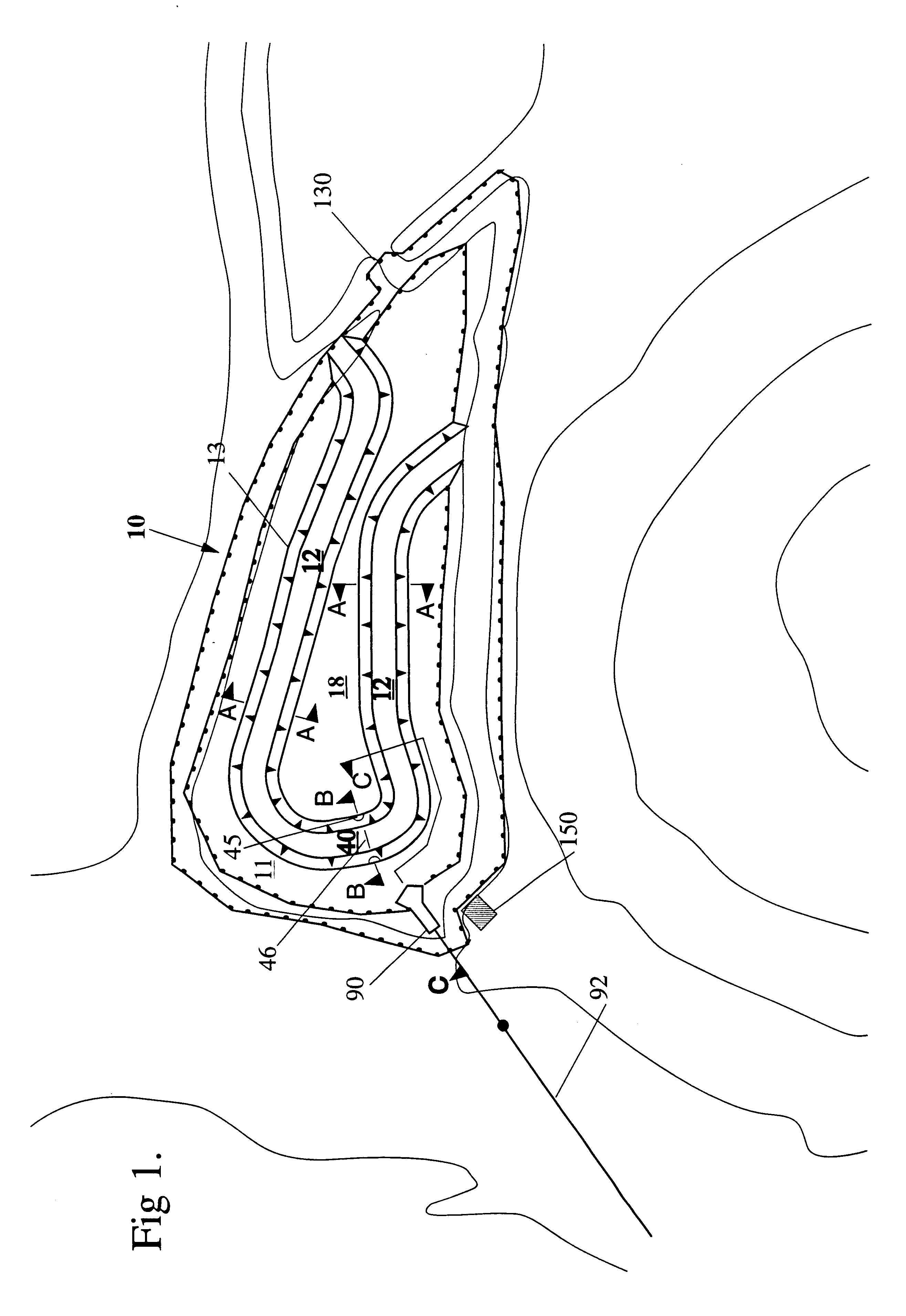
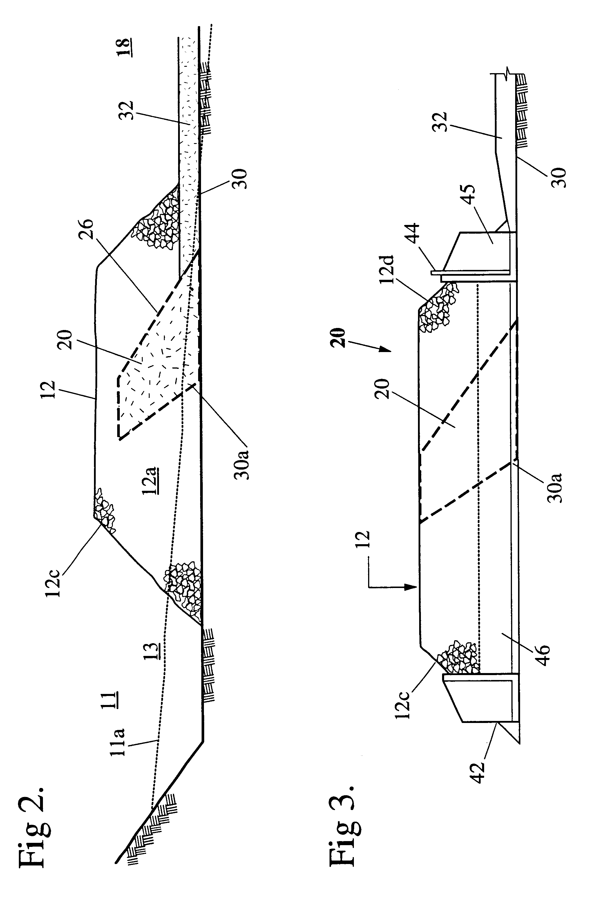
FIGS. 1 and 2 show a water treatment system 10 comprising a water permeable wall portion 12 defining a water treatment portion 18 of a waterway to be treated; and a treating portion 20 retained at a desired position within the wall portion 12 by retaining means 26. By a "desired position" is intended a location such that the requisite degree of treatment as set by water treatment standards or otherwise may be achieved, all other factors being equal. Water to be treated permeates through the wall portion 12 and retaining means 26 to the treating portion for removing pollutants contained therein prior to discharge of water from the system 10. FIGS. 2 to 6 provide sectional views of particular portions of wall 12.

In the preferred embodiment, as shown in FIGS. 1 to 6, the water treatment system 10 is intended to treat stormwater or floodwater which passes through a watercourse following heavy rainfall and storm events. Expected flowrates will range between 0.08 m.sup.3 (2.7 ft 3 / .sub.s)...


PUM

PropertyMeasurementUnit
Pore sizeaaaaaaaaaa
Permeabilityaaaaaaaaaa
Porosityaaaaaaaaaa

Abstract

Disclosed is a water treatment system (10) including:(a) a water permeable wall portion (12) defining a water treatment portion (18) of a waterway to be treated; and(b) a treating portion (20) retained in a desired position relative to the permeable wall portion (12) by retaining means (26) wherein water to be treated permeates through said wall portion (12), said retaining means (26) and said treating portion (20) for removing pollutants contained therein prior to discharge of water from the system (10).

Description

This invention relates to water treatment systems and, in particular, to treatment of waterways and aquatic systems such as wetlands which may become subject to contamination with pollutant rich, for example nutrient rich, run off and other effluent waters. The invention further relates to an improved water treatment method.BACKGROUND TO THE INVENTIONWaterways, such as wetlands, rivers, creeks, flood prone areas and so on are subject to various sources of pollution. Significant among these are rain or stormwater flows which may become contaminated with various contaminants and pollutants which exist in the wider environment. Key among these pollutants are the nutrients phosphorus and nitrogen present in agricultural fertilisers. Other sources of pollution include particulate matter, other organochemicals and metals.It has been recognised that stormwater is especially polluting in the early time phase following a storm. International Patent Application No. WO 97 / 41068, assigned to CS...

Claims


Application Information

Patent Timeline
IPC IPC(8): B01D24/00B09C1/00C02F1/28C02F3/06
CPCB01D24/007B09C1/002B01D24/20C02F1/281C02F3/06C02F2101/105C02F2103/06C02F2103/001C02F2103/007Y02W10/10
Inventor BOWMAN, MARTIN
Owner ECOLOGIC HLDG (PTY) LTD
Features
  • Generate Ideas
  • Intellectual Property
  • Life Sciences
  • Materials
  • Tech Scout
  • Unparalleled Data Quality
  • Higher Quality Content
  • 60% Fewer Hallucinations
Learn More