
Loop heat pipe incorporating an evaporator having a wick that is liquid superheat tolerant and is resistant to back-conduction

a loop heat pipe and evaporator technology, applied in the direction of insulated conductors, semiconductor/solid-state device details, cables, etc., can solve the problems of large temperature gradients across the wick, static height differentials, or other forces that are too great to allow proper heat transfer, and the cylindrical geometry of the cylindrical evaporator

Inactive Publication Date: 2002-05-07
NORTHROP GRUMMAN INNOVATION SYST INC
View PDF18 Cites 155 Cited by
  • Summary
  • Abstract
  • Description
  • Claims
  • Application Information

AI Technical Summary

Problems solved by technology

This is a typical thermal engineering problem encountered in a wide range of applications including building environmental conditioning systems, spacecraft thermal control systems, the human body, and electronics.
In other applications, however, the pressure differential due to fluid frictional losses, static height differentials, or other forces may be too great to allow for proper heat transfer.
Second, decreased back-conduction would allow the evaporator operating temperature to approach sink temperature, particularly at low power.
Third, decreased back-conduction would allow loop heat pipes to operate at low vapor pressure, where the low slope of the vapor pressure curve allows small pressure differences in the loop to result in large temperature gradients across the wick.
Aside from any back-conduction considerations, another inherent disadvantage of the cylindrical evaporator is its cylindrical geometry, since many cooling applications call for transferring heat away from a heat source having a flat surface.
This presents a challenge of how to provide for good heat transfer between the curved housing of a cylindrical evaporator and a flat surfaced heat source.
Increasing the number of evaporators increases the cost and complexity of the heat transport system.
The plates are sealed together, which often requires use of bulky clamps or thick plates.
Clamps, thick plates and added support mechanisms have the disadvantages of unnecessary weight, thickness and complexity.
The main disadvantages of support structures such as studs, bars, ribs, and the like (i.e., Sarraf et al., Basiulis, Marcus et al., and Owen) and bulky walls (i.e., Edelstein et al.) are that they add weight to the evaporators.
The Meyer, IV et al. disclosure does not address the issues of containment of high-pressure working fluids in flat capillary evaporators.
The conventional schemes do not have the low weight to heat transferred ratio characteristic of LHP technology.
Unfortunately, prior art LHPs have not provided for a way to reduce back-conduction, which is often large due to the hydrostatic pressure caused by height differentials that arise in terrestrial applications.
That is to say, gravity causes hydrostatic pressure, which increases the temperature gradient across the wick, which increases back-conduction, and high back conduction limits LHP design choices by requiring high-pressure working fluids.
Prior art LHPs are bulky, with an evaporator and condenser that tend to be physically distanced from one another.
However, these prior art LHP configurations are not well suited for applications where the heat input surface and the heat output surface are intimately close to one another.
Altering one aspect to favor performance often has an adverse effect on another aspect.
Both the pressure range and corrosion are primarily affected by the choice of working fluid.
As discussed above in the background section, loop heat pipes for terrestrial use have been problematic in the prior art.
The primary problem has been the inability to use water or other fluids with low vapor pressure in the presence of gravity because of excessive back-conduction.

Method used


Image

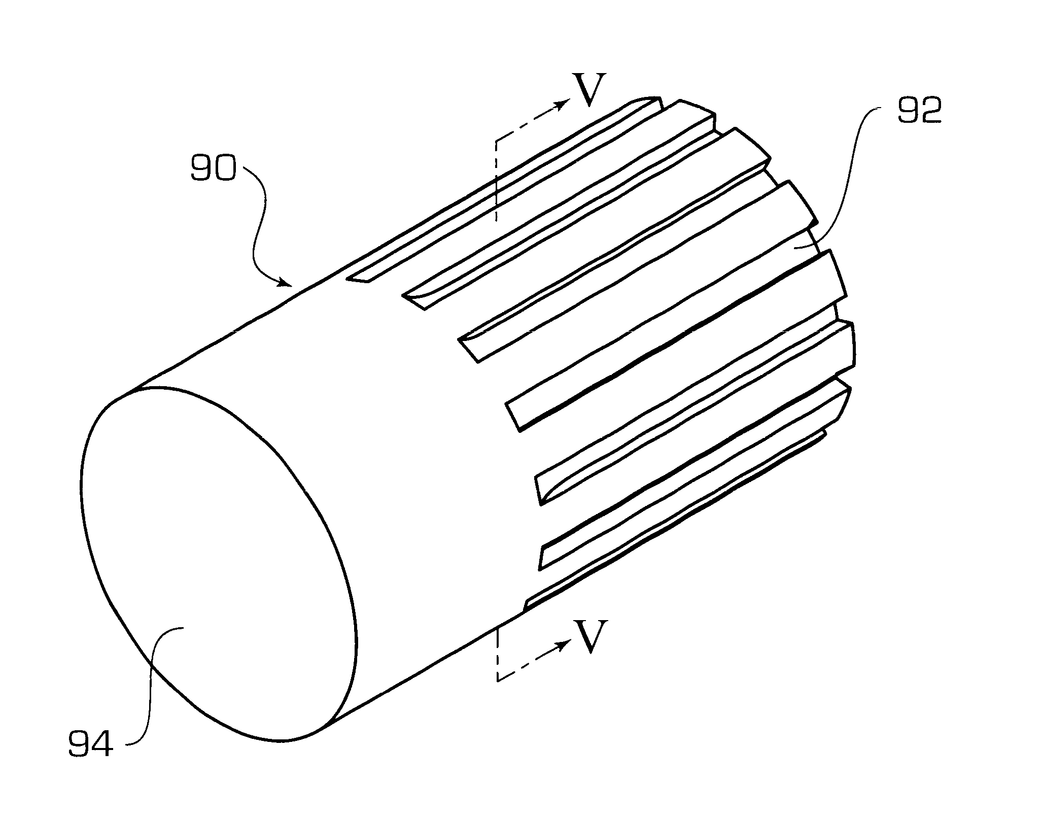
  • Loop heat pipe incorporating an evaporator having a wick that is liquid superheat tolerant and is resistant to back-conduction
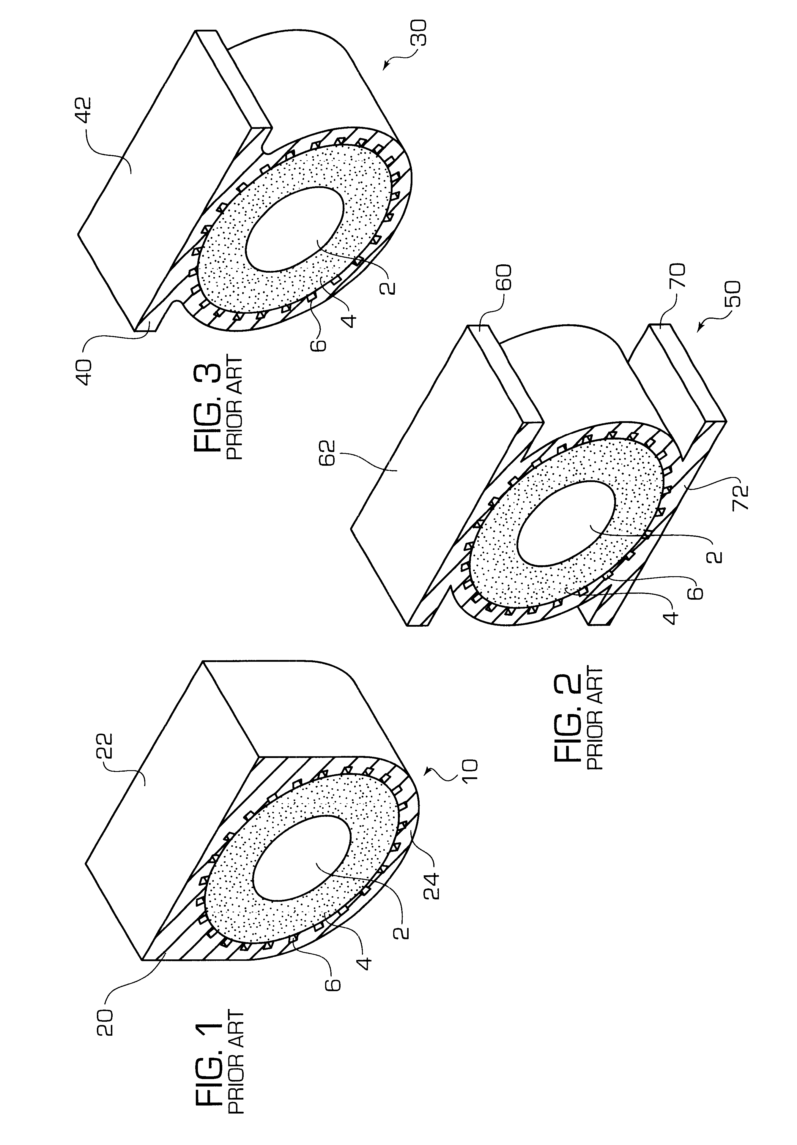
  • Loop heat pipe incorporating an evaporator having a wick that is liquid superheat tolerant and is resistant to back-conduction
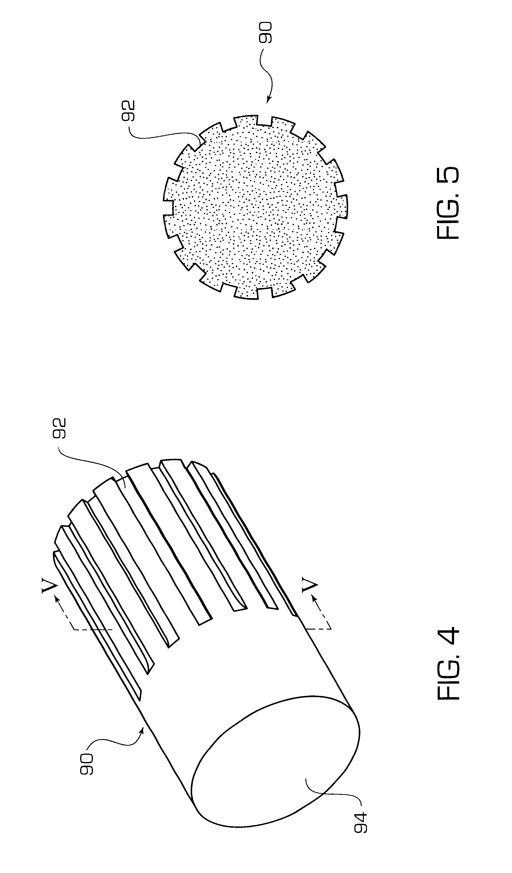
  • Loop heat pipe incorporating an evaporator having a wick that is liquid superheat tolerant and is resistant to back-conduction

Examples


Embodiment Construction

working example according to a flat capillary evaporator embodiment of the present invention is described as follows.

Ammonia is chosen as the working fluid. This is a high-pressure working fluid. The vapor pressure of ammonia at 60.degree. C. is 2600 kPa. Accordingly, the tensile strength of the wick and the bond should be at least about 6500 kPa. The wick is stainless steel because of its high strength properties and its resistance to corrosion in an ammonia environment.

The active length of the heat input surface of the evaporator is 2 inches. A high heat flux of 40 W / in..sup.2 over 0.25 in. is located near the liquid manifold, with a load of 1 W / in..sup.2 over the remainder of the heat input surface.

Referring to FIG. 18, performance curves for the exemplary flat plate evaporator are illustrated on a graph. The thin solid line curve represents available capillary pressure rise (.DELTA.P.sub.CAPILLARY), the broken line curve represents evaporator pressure drop (.DELTA.P.sub.DROP), a...


PUM

PropertyMeasurementUnit
melting pointaaaaaaaaaa
lengthaaaaaaaaaa
taper angleaaaaaaaaaa

Abstract

A capillary wick for use in capillary evaporators has properties that prevent nucleation inside the body of the wick, resulting in suppression of back-conduction of heat from vapor channels to the liquid reservoir. Use of a central liquid flow channel in the wick is eliminated, and pore size in the wick is chosen to maximize available pressure for fluid pumping, while preventing nucleation in the wick body. The wick is embodied with different geometries, including cylindrical and flat. A flat capillary evaporator has substantially planar heat input surfaces for convenient mating to planar heat sources. The flat capillary evaporator is capable of being used with working fluids having high vapor pressures (i.e., greater that 10 psia). To contain the pressure of the vaporized working fluid, the opposed planar plates of the evaporator are brazed or sintered to opposing sides of a metal wick. Additionally, a terrestrial loop heat pipe and a loop heat pipe having overall flat geometry are disclosed.

Description

1. Field of the InventionThe present invention relates generally to the field of heat transfer. More particularly, the present invention relates to wicks for use in loop heat pipe evaporators.2. Background InformationThere are numerous instances where it is desirable to transfer heat from a region of excess heat generation to a region where there is too little heat. The object is to keep the region of heat generation from getting too hot, or to keep the cooler region from getting too cold. This is a typical thermal engineering problem encountered in a wide range of applications including building environmental conditioning systems, spacecraft thermal control systems, the human body, and electronics.A variety of techniques can be employed to achieve this heat sharing effect. These include heat straps (simple strips of high conductivity material), closed loops of pumped single-phase fluid, heat pipes, mechanically pumped two-phase loops, and capillary pumped two-phase loops.The most a...

Claims


Application Information

Patent Timeline
Patent Type & Authority Patents(United States)
IPC IPC(8): F28D15/02F28D15/04F28D15/00
CPCF28D15/0233F28D15/043F28D15/04F28D15/046Y10T29/49353
Inventor KROLICZEK, EDWARD J.WRENN, KIMBERLY R.WOLF, SR., DAVID A.
Owner NORTHROP GRUMMAN INNOVATION SYST INC
Learn More