Method and Circuit for testing devices with serial data links

a technology of serial data and testing method, applied in the direction of frequency-division multiplex, transmission monitoring, receiver monitoring, etc., can solve the problems of difficult to determine, difficult to test, and difficult to determine easy to fail tests

Inactive Publication Date: 2002-05-07
AVAGO TECH INT SALES PTE LTD
View PDF21 Cites 73 Cited by
  • Summary
  • Abstract
  • Description
  • Claims
  • Application Information

AI Technical Summary

Benefits of technology

It is an object of the present invention to provide a circuit which makes it possible to test a transceiver which is incorporated in a finished product, such as in a hard disk drive, a printer, a digital camera, etc., without having to open or otherwise disassemble the product.
It is a further object of the present invention to provide a method which effectively improves the testability of products with serial data links.
Such a method and configuration makes it possible to test a transceiver which is incorporated in a finished product, such as in a hard disk drive, a printer, a digital camera, etc., without having to open or otherwise disassemble the product.

Problems solved by technology

When a device with a serial data link fails, generally there is no easy way to determine whether the failure was caused by the serial transceiver of the serial data link, or by other components in the device.
If the data actually written to the disk is inconsistent with the data which was originally communicated to the disk drive through the 1394 serial data link (i.e. there is corruption), it is generally relatively difficult to determine, without opening the cover of the disk drive and testing each individual component, if the inconsistency (i.e. failure) was caused by a transceiver which malfunctioned, or instead by some other component of the disk drive.
However, once a transceiver is incorporated into the finished product, generally there is no easy way to test the transceiver.
This is because the parallel interface of the transceiver is usually connected directly to a controller, as discussed above, and the transceiver is not accessible without opening the case.
Consequently, should the finished product fail, it is generally relative difficult to determine whether the failure has occurred as a result of a transceiver which has malfunctioned.
The usefulness of such a loopback is somewhat limited due to the fact that the quality of the signal, such as its amplitude, rise and fall time, jitter, etc., cannot be controlled to any great extent.
Furthermore, this type of loopback does not provide that a bit error rate test, as described above, can be performed on a transceiver which is incorporated in a finished product.

Method used


Image

  • Method and Circuit for testing devices with serial data links
  • Method and Circuit for testing devices with serial data links

Examples


Embodiment Construction

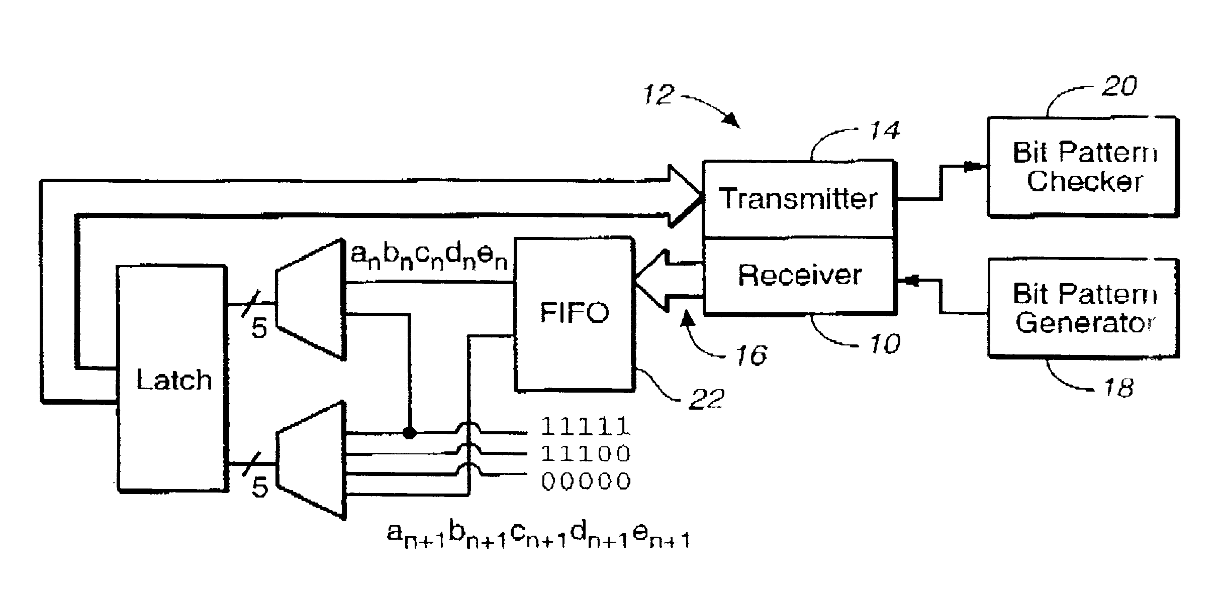
Embodiments in accordance with the present invention include circuits and methods which can be used to determine whether a failure has been caused by a transceiver which has malfunctioned.

As discussed above, a loopback function is sometimes used in association with a transceiver to perform some relatively basic self-test functions, and the loopback function effectively loops back the signal at the serial data interface. The loopback configuration provides that the transmitter portion of the transceiver is connected to the receiver portion of the same transceiver through a serial cable. As discussed above, the usefulness of such a loopback is somewhat limited due to the fact that the quality of the signal cannot be controlled to any great extent. Additionally, this type of loopback configuration does not provide that a transceiver can be tested in a finished product without having to open the case of the product or otherwise disassemble the product.

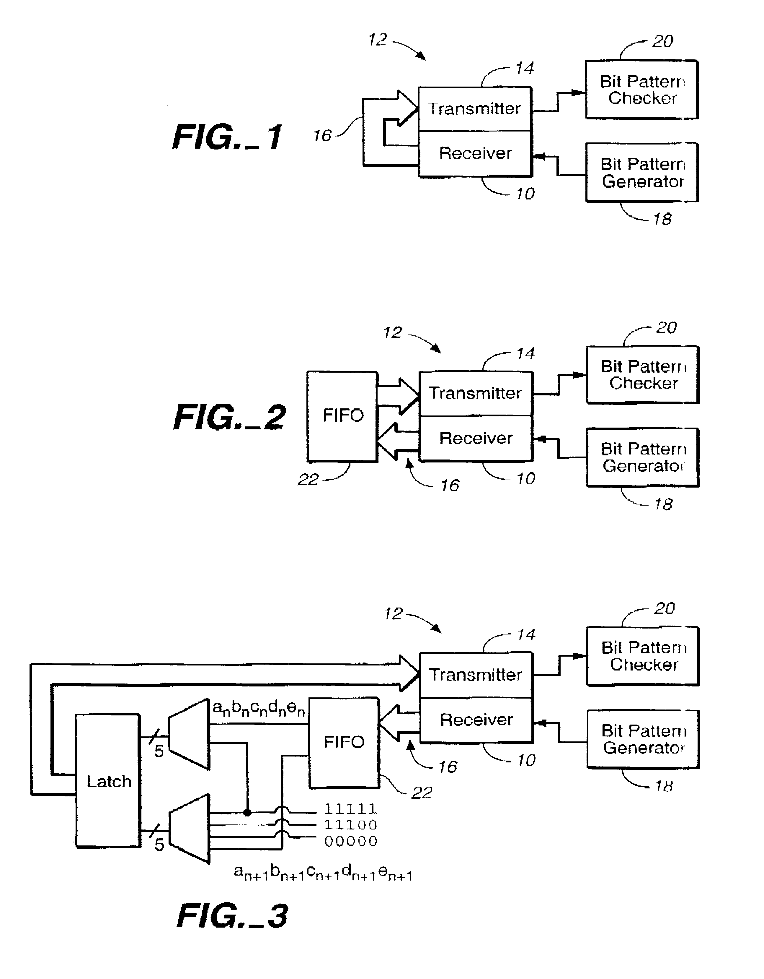
In contrast, FIG. 1 illustrates a l...


PUM


Abstract

A circuit and method for testing a transceiver. The circuit includes a bit pattern generator connected to the transceiver such that the bit pattern generator can communicate a serial data stream to a receiver portion of the transceiver. The circuit also includes a bit pattern checker connected to the transceiver such that a transmitter portion of the transceiver can communicate a serial data stream to the bit pattern checker. The transceiver is configured such that the receiver portion of the transceiver is communicatingly looped back to the transmitter portion of the transceiver such that a data stream can be communicated from the receiver portion of the transceiver to the transmitter portion of the transceiver. Desirably, a loopback circuit in connected to the transceiver and includes fixed bit pattern means for communicating at least one fixed bit pattern to the transmitter portion of the transceiver. The loopback circuit is configured such that the FIFO component receives a set of bits from the receiver portion of the transceiver and at least one of the bits in the set is replaced by the fixed bit pattern before being communicated to the transmitter portion of the receiver.

Description

The present invention relates generally to circuits and methods for testing devices, and relates more specifically to a circuit and method which can be used to test products with serial data links, such as transceivers, thereby improving the testability of these devices.Some examples of devices or products which generally include serial data links include hard disk drives, printers, digital cameras, etc. Generally, a serial data link provides that a transceiver is located at each end of a serial cable. Each transceiver transmits and receives signals, and is connected to a controller through a parallel interface. The transmitter of each transceiver receives parallel data (i.e. data in a parallel data stream) from the respective controller to which that transceiver is connected, converts the data into a serial data stream, and then transmits the serial data into the cable and to the other transceiver. The receiver of the other transceiver receives the incoming serial data stream, reco...

Claims


Application Information

Patent Timeline
Patent Type & Authority Patents(United States)
IPC IPC(8): H04B17/00
CPCH04L1/243H04B17/20H04B17/10
Inventor CHEN, DAO-LONG
Owner AVAGO TECH INT SALES PTE LTD
Why Eureka
Try Eureka