Micro-scalable thermal control device

a thermal control device and micro-scalable technology, applied in the field of micro-scalable thermal control devices, can solve the problems of difficult miniaturization of many of these traditional heating and cooling devices, the limitations of micro-scale and traditional scale thermal control devices, etc., and achieve the effect of heating or cooling a relatively large surface area

Inactive Publication Date: 2002-05-14
NAT AERONAUTICS & SPACE ADMININSTRATION UNITED STATES OF AMERICA THE AS REPRESENTED BY THE SEC
View PDF5 Cites 31 Cited by
  • Summary
  • Abstract
  • Description
  • Claims
  • Application Information

AI Technical Summary

Benefits of technology

It is a further object of an exemplary form of the present invention to provide a modular thermodynamic device that is capable of achieving and maintaining a designated steady state temperature in the associated device.
It is a further object of an exemplary form of the present invention to provide a modular thermodynamic device that is capable of being used in series with other modular thermodynamic devices to provide wider range of temperatures to which the associated device can be heated or cooled.
It is a further object of an exemplary form of the present invention to provide a modular t

Problems solved by technology

It has been difficult to miniaturize many of these traditional heating and cooling devices.
This is because the material and means of manufacture of the traditional components of these devices, such as the pistons, linkages, and pressure vessels of a traditional Stirling cooler, for example, are generally not suited for microscale production.
In addition to the difficulties of miniaturization, most heat transfer systems act either to cool or to heat, but not both.
This limitation applies both to microscale and traditional scale thermal control devices.
Sti

Method used


Image

  • Micro-scalable thermal control device
  • Micro-scalable thermal control device
  • Micro-scalable thermal control device

Examples


Embodiment Construction

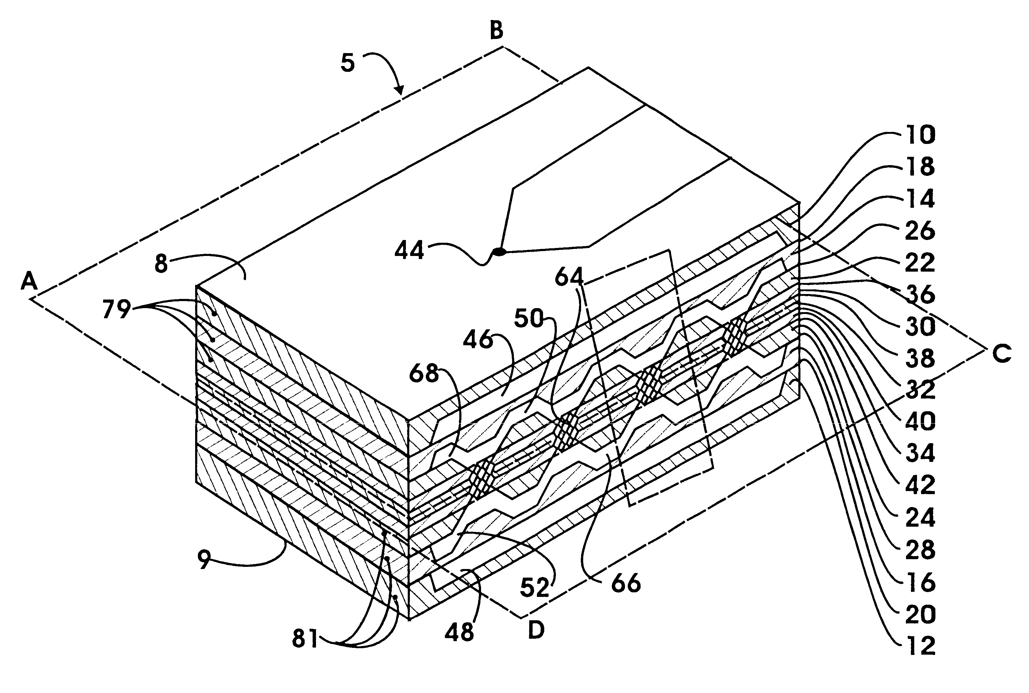
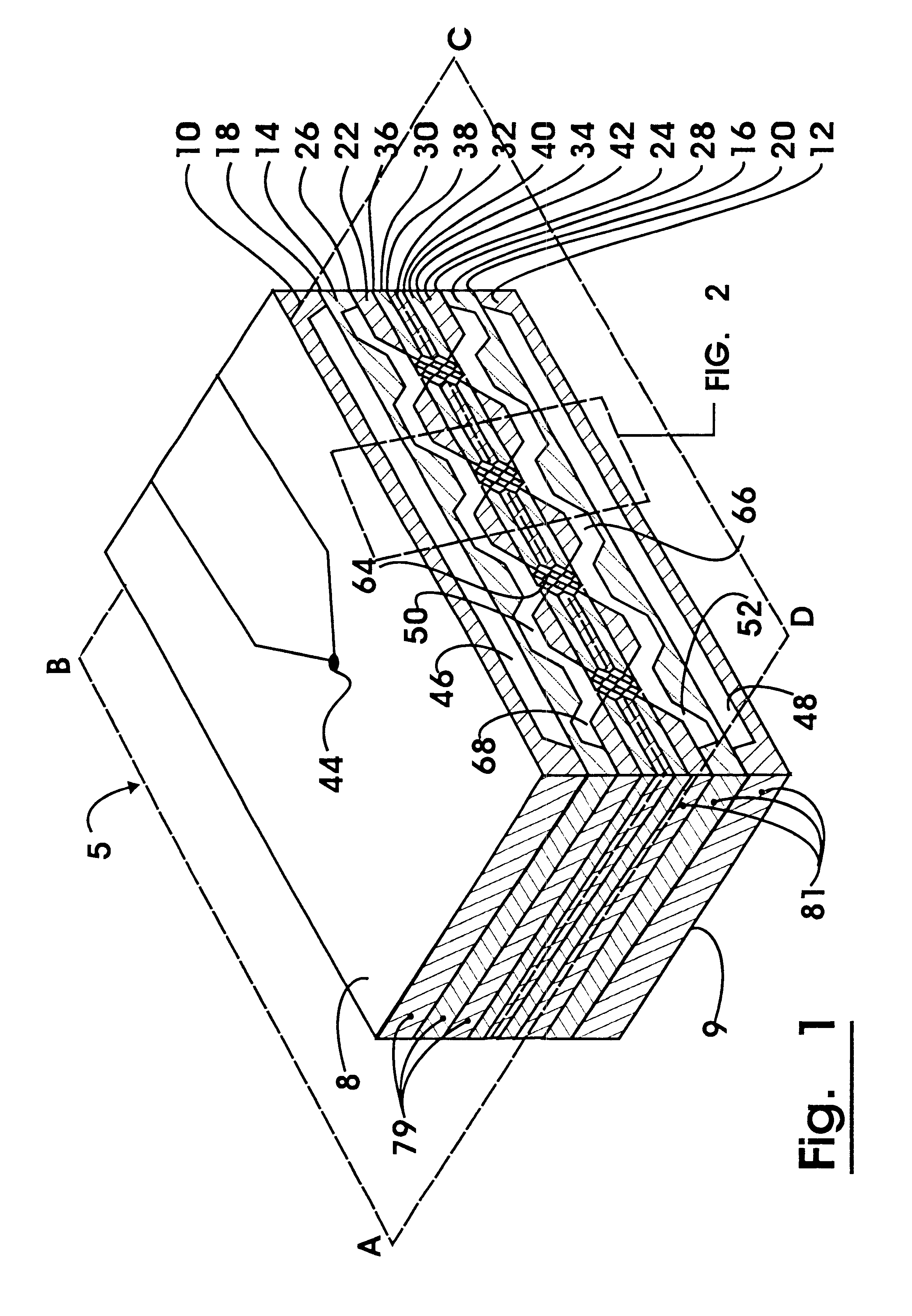
Referring now to the drawings, in particular to FIG. 1, there is shown therein a first exemplary embodiment of a microscalable temperature control module generally referred to by reference numeral 5. Module 5 comprises a plurality of rectangular layers. Portions of all functional layers are removed to give module 5 an internal structure, described in more detail below.

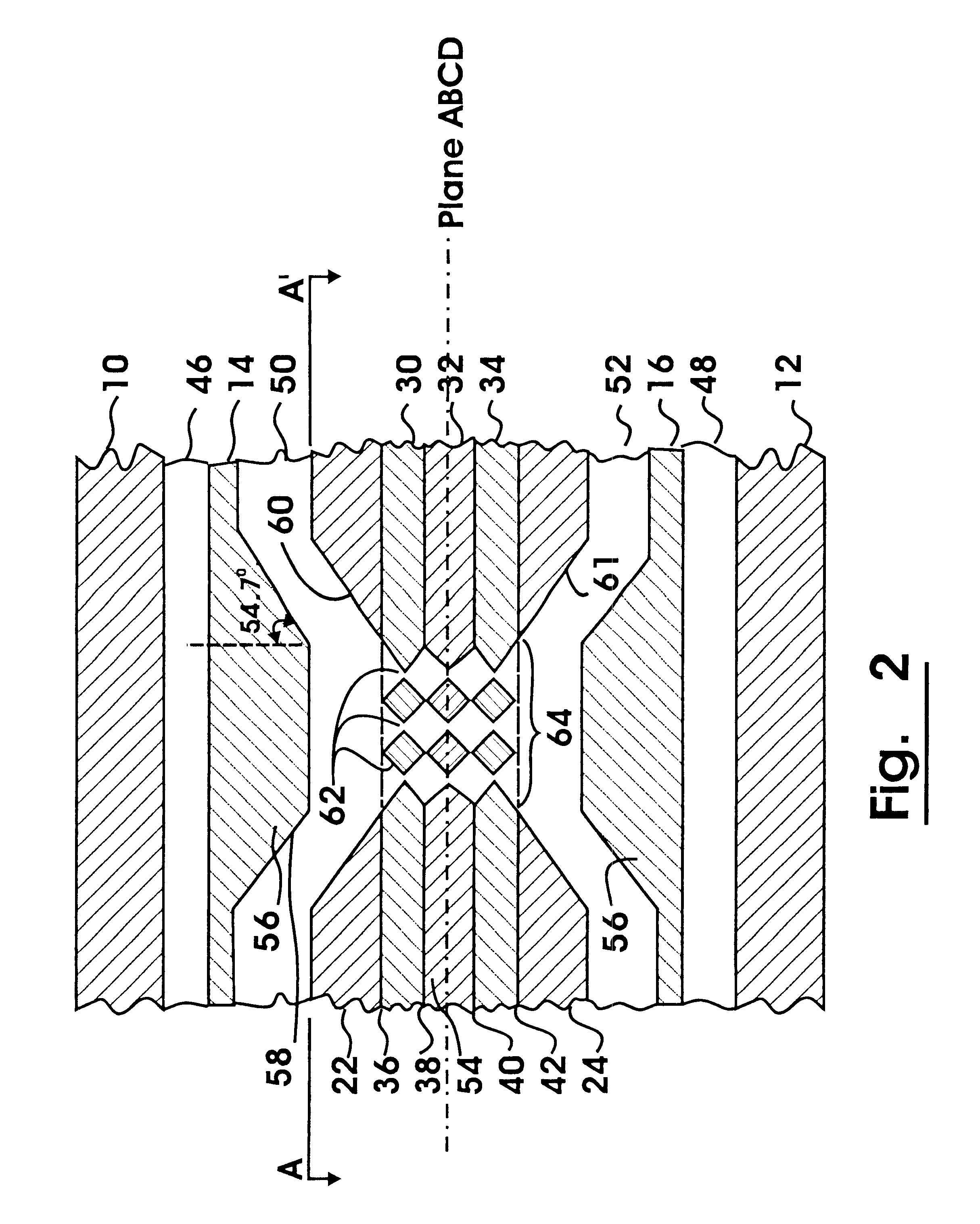
Module 5, in an exemplary embodiment shown, is symmetric with respect to a plane ABCD that is parallel to the layers and that passes through the longitudinal center of a module 5. Module 5 is bounded by a first thermal energy transfer layer 10, and second thermal energy transfer layer 12.

Interior and adjacent to the first thermal energy transfer layer 10 is a first diaphragm layer 14. Similarly, interior and adjacent to the second thermal energy transfer layer 12 is a second diaphragm layer 16. Interposed between the first thermal energy transfer layer 10 and the first diaphragm layer 14, at all points of contact betwe...


PUM


Abstract

A microscalable thermal control module consists of a Stirling cycle cooler that can be manipulated to operate at a selected temperature within the heating and cooling range of the module. The microscalable thermal control module is particularly suited for controlling the temperature of devices that must be maintained at precise temperatures. It is particularly suited for controlling the temperature of devices that need to be alternately heated or cooled. The module contains upper and lower opposing diaphragms, with a regenerator region containing a plurality of regenerators interposed between the diaphragms. Gaps exist on each side of each diaphragm to permit it to oscillate freely. The gap on the interior side one diaphragm is in fluid connection with the gap on the interior side of the other diaphragm through regenerators. As the diaphragms oscillate working gas is forced through the regenerators. The surface area of each regenerator is sufficiently large to effectively transfer thermal energy to and from the working gas as it is passed through them. The phase and amplitude of the oscillations can be manipulated electronically to control the steady state temperature of the active thermal control surface, and to switch the operation of the module from cooling to heating, or vice versa. The ability of the microscalable thermal control module to heat and cool may be enhanced by operating a plurality of modules in series, in parallel, or in connection through a shared bottom layer.

Description

This invention relates generally to heat transfer systems. Specifically, this invention relates to microscale Stirling cycle devices, which may be used to heat, cool, or maintain a steady temperature in associated items such as electronics, sensors, microelectromechanical system (MEMS) devices, or spacecraft components.The development of electronics and microelectromechanical systems has been accompanied by the need for systems of similar small size to control the temperature of these items. Some of the systems that have been used for temperature control of devices of any size have included natural convection enhancements, conduction enhancements, radiation enhancements, forced air systems, liquid cooling loops, heat pipes, thermoelectric devices, standard thermodynamic cycle devices, resistance heaters, combustion heaters, and various combinations thereof. Devices of these types have historically been large, when compared to the sizes of microelectronic or MEMS devices. It has been...

Claims


Application Information

Patent Timeline
IPC IPC(8): F02G1/00F02G1/043F25B9/14
CPCF02G1/043F25B9/14F25B2400/15F02G2250/31
Inventor MORAN, MATTHEW E.
Owner NAT AERONAUTICS & SPACE ADMININSTRATION UNITED STATES OF AMERICA THE AS REPRESENTED BY THE SEC
Why Eureka
Try Eureka