Antenna-integrated microwave-millimeter wave module

a technology of microwave-millimeter wave module and antenna, which is applied in the direction of resonant antennas, individual energised antenna arrays, and semiconductor/solid-state device details, etc., and can solve the problem of extremely difficult fabrication of such antennas

Inactive Publication Date: 2002-05-14
SHARP KK
View PDF8 Cites 40 Cited by
  • Summary
  • Abstract
  • Description
  • Claims
  • Application Information

AI Technical Summary

Problems solved by technology

Consequently, a feeding circuit has a complicated str...

Method used


Image

  • Antenna-integrated microwave-millimeter wave module
  • Antenna-integrated microwave-millimeter wave module
  • Antenna-integrated microwave-millimeter wave module

Examples


example 2

Samples were actually prepared as Example 1 by employing, as adhesive (resin) to be applied onto the surface of a plurality of slot holes 10, fluorine-based resin having a smaller dielectric constant (2.9) than that of silicone resin and laminating multilayer substrate 1 and organic substrate 7. Resultant measurements are shown in Table 2.

It can be understood from comparison between Table 1 and Table 2 that a higher efficiency can be achieved by employing the fluorine-based resin (resin containing fluorine) having a lower dielectric constant as shown in Table 2 with respect to the same thickness of organic substrate 7 (450 .mu.m, 600 .mu.m) and the same thickness of the adhesive layer (100 .mu.m).

The foregoing discussion on this embodiment does not limit the present invention to a particular form herein described. For example, the invention is applicable to any frequency band except for 60 GHz band. In particular, for the frequency band ranging from 50 to 70 GHz, the structure as he...


PUM


Abstract

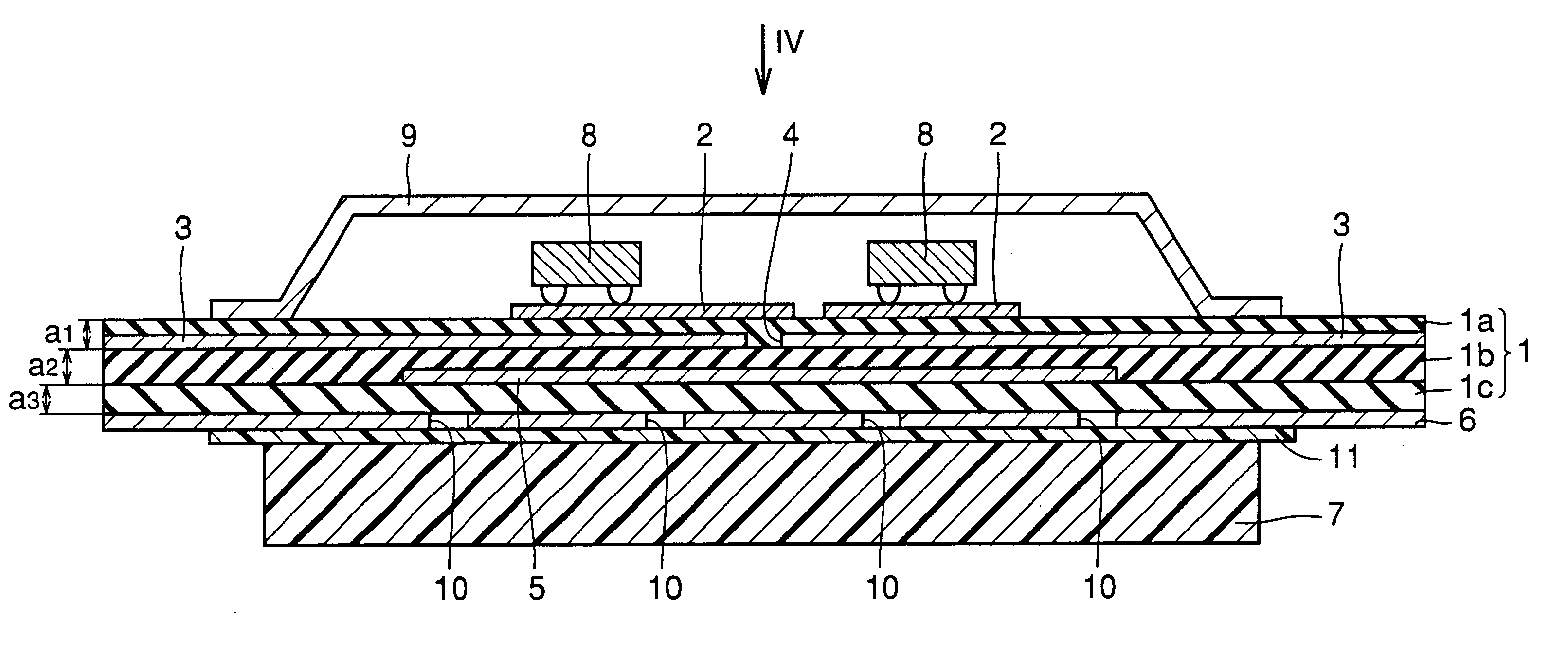
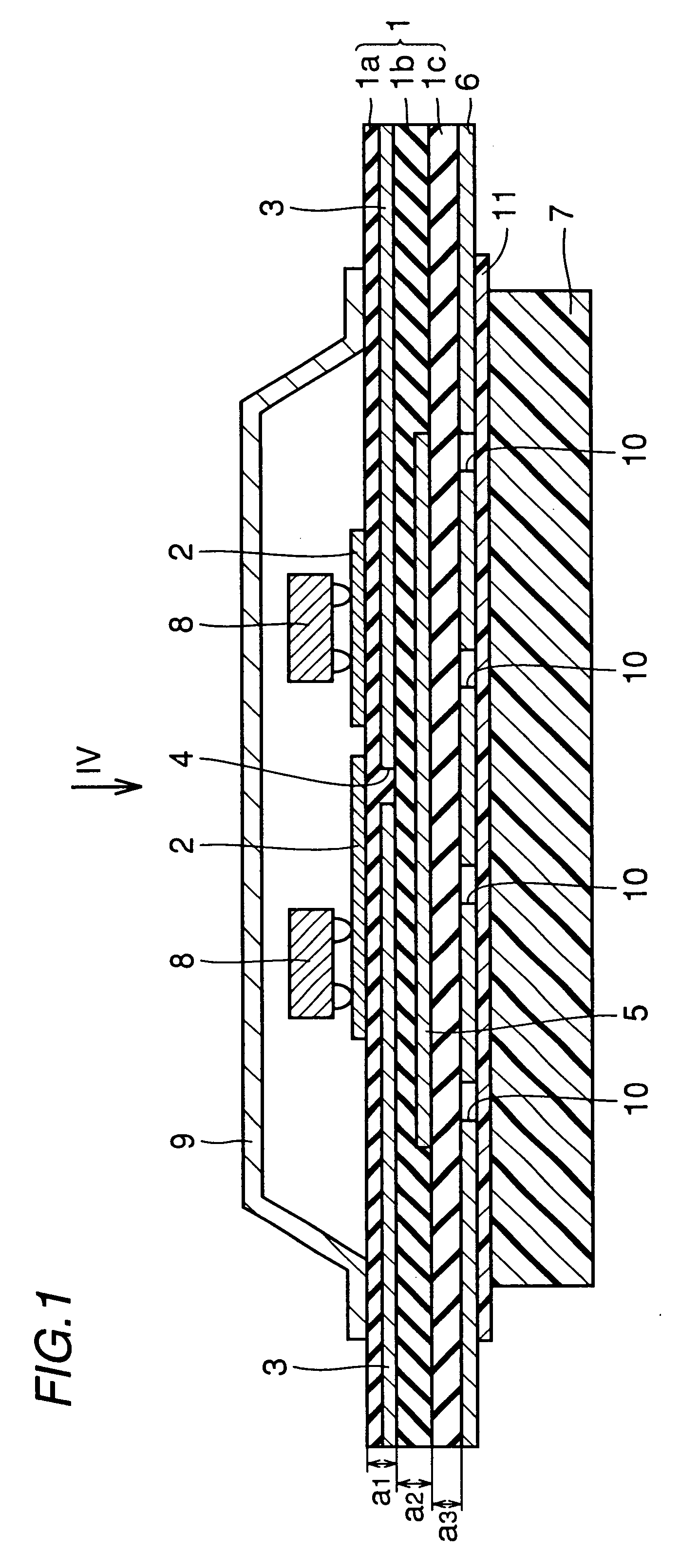
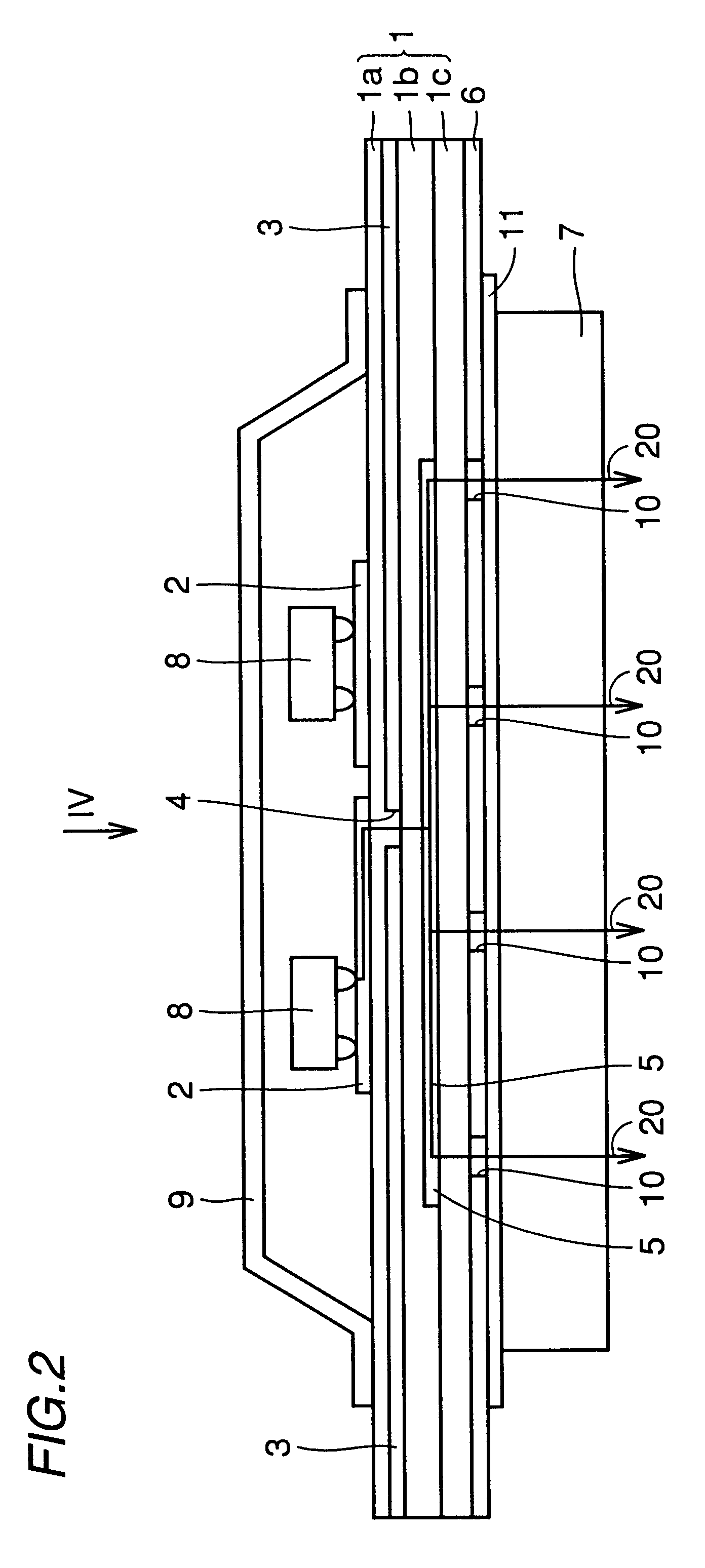
A microwave circuit or a millimeter wave circuit is formed on a semiconductor chip. A multilayer substrate is formed of a first dielectric layer, a second dielectric layer and a third dielectric layer. A high-frequency circuit line with the semiconductor chip mounted thereon is formed on the third dielectric layer. A slot hole is formed on one side of the second dielectric layer and an antenna feeding line is formed on the other side. The first dielectric layer has a plurality of slot holes formed therein that radiate electromagnetic waves. An organic substrate is laminated to the multilayer substrate by an adhesion layer.

Description

1. Field of the InventionThe present invention relates to a structure of an antenna-integrated microwave-millimeter wave module and particularly to a microwave-millimeter wave module integrated with a slot antenna having improved antenna efficiency and directivity.2. Description of the Background ArtWith recent increase in information amount, radio communication by high frequencies like microwave and millimeter wave has been attracting attention as high-speed and high-capacity data transmission means. This type of communication requires an antenna and a microwave-millimeter wave circuit that are integrated, i.e., an antenna-integrated microwave-millimeter wave circuit of small size, lightweight and high performance to serve as a transmitter-receiver.Conventional slot antennas are structured by providing a slot placed opposite an open end of a strip conductor of a microstrip line with a dielectric therebetween and electromagnetically coupling the microstrip line and the slot.FIGS. 6 ...

Claims


Application Information

Patent Timeline
IPC IPC(8): H01Q13/10H01Q23/00H01Q21/06H01Q1/32H01P5/02
CPCH01Q1/3233H01Q23/00H01Q21/064H01Q13/106H01L2224/16225H01L2924/16152
Inventor SAKOTA, NAOKIYAMADA, ATSUSHIKITAOKA, KOKI
Owner SHARP KK
Why Eureka
Try Eureka