
Machine for producing and/or treating a material web

a technology of a material web and a machine body, which is applied in the direction of drying, lighting and heating equipment, washing apparatus, etc., can solve the problem of closing off the cooling and heating medium spa

Inactive Publication Date: 2002-06-04
VOITH SULZER PAPIERTECHN PATENT
View PDF16 Cites 6 Cited by
  • Summary
  • Abstract
  • Description
  • Claims
  • Application Information

AI Technical Summary

Benefits of technology

On the basis of this design, an extremely reliable seal of the region occupied by the material web and the at least one wire, and / or of the pressure chamber of the overpressure cap, is achieved with minimal cost in a simple manner. An underpressure can be created or maintained with the relevant seal of the region occupied by the material web and the wire, which results in an increase in drying performance. Moreover, entry of the liquid or gaseous medium is prevented. Because of the appropriate sealing of the pressure chamber of the overpressure cap, a structural pressure can be applied which results not only in greater drying performance, but also in improved paper characteristics.
It is also advantageous for the opposing edges or side walls of the recess to be coated with a material that is heat resistant, flexible, and seals well, for example such as Teflon, silicone, or the like. In this way, sealing the space between the heatable unit and the material web is significantly improved, and the steam pressure produced in this space during drying is increased. Accordingly, the quantity of water expelled from the material web is also increased, and the drying performance is improved for the same heat output.
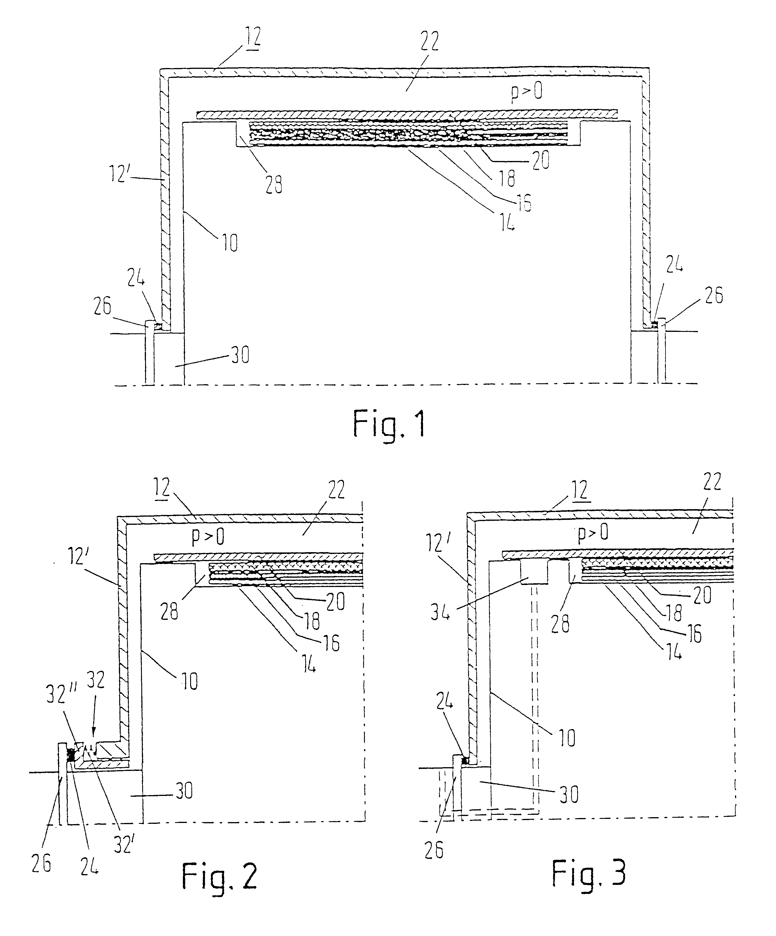
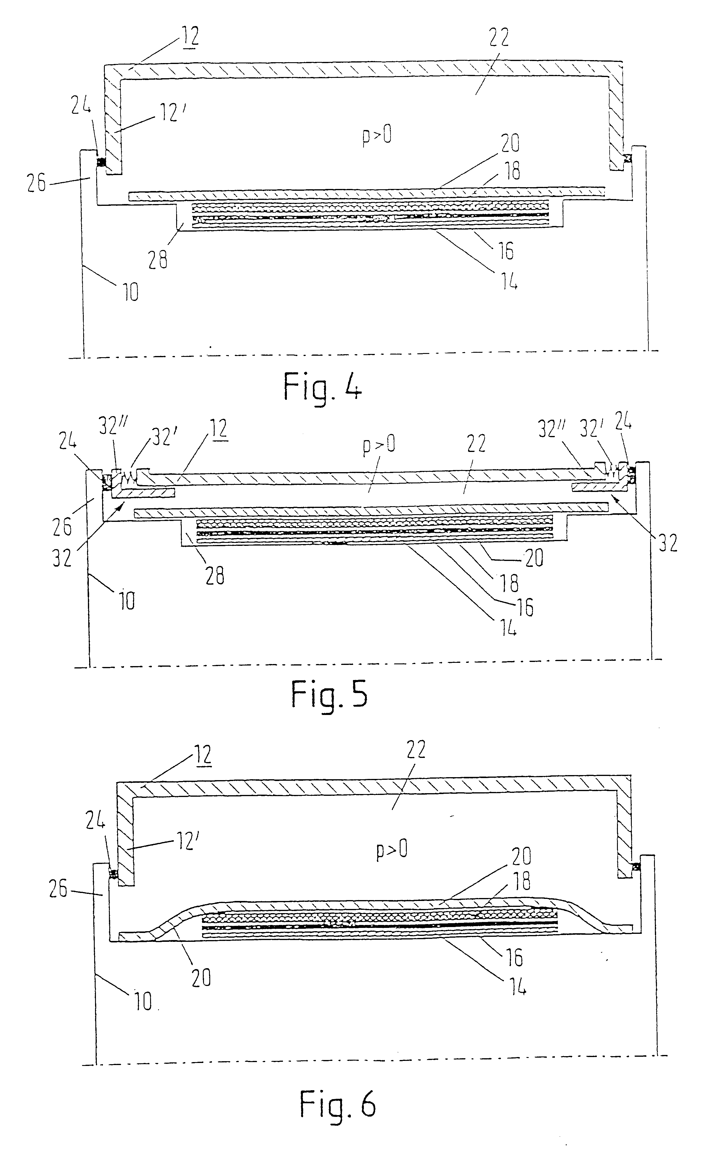
For an even more reliable seal of the region occupied by the material web and the wire, it is useful to provide at least one sealing pocket or chamber opposite each lateral edge region of the sealing belt and covered thereby. It is advantageous for at least one sealing pocket or chamber to be located opposite each of the two lateral edge regions of the sealing belt. In certain cases, it can be useful for at least two sealing pockets or chambers to be located opposite at least one of the two edge regions of the sealing belt.
In another advantageous embodiment, at least one cylinder-side opposing wall is formed by a shoulder provided in the vicinity of each bearing journal of the heatable unit, and the relevant end face of the overpressure cap is extended to the region of this bearing journal. For example, the seal can be located in the vicinity of the bearing journal or at some point in the middle. In this case as well, the sealing force can again be applied by the preloading of the cap as a result of the internal pressure, or mechanically. As a result of the fact that the relevant opposing wall and the seal are located in the vicinity of the bearing journal, the relative speed between the rotating and the stationary part is lower, which reduces wear on the seal accordingly.
It is advantageous for at least one end face of the heatable unit to be provided with a heat-resistant material, which reduces to a minimum the direct flow of heat between the heatable unit and the cold coolant.
According to a further aspect of the invention, a heat transfer effect occurs from the at least heatable unit toward the sealing belt. According to a still further aspect of the present invention, the process further includes relieving a pressure, buildup between the sealing belt and the at least one heatable unit to an external atmosphere using at least one of a channel, bore, and passageway.

Problems solved by technology

The space for the cooling and heating medium is closed off by costly seals such as, in particular, flat surfaces with high speeds relative to the steel belts traveling along with the paper web.

Method used


Image

  • Machine for producing and/or treating a material web
  • Machine for producing and/or treating a material web
  • Machine for producing and/or treating a material web

Examples


Embodiment Construction

The particulars shown herein are by way of example and for purposes of illustrative discussion of the embodiments of the present invention only and are presented in the cause of providing what is believed to be the most useful and readily understood description of the principles and conceptual aspects of the present invention. In this regard, no attempt is made to show structural details of the present invention in more detail than is necessary for the fundamental understanding of the present invention, the description taken with the drawings making apparent to those skilled in the art how the several forms of the present invention may be embodied in practice.

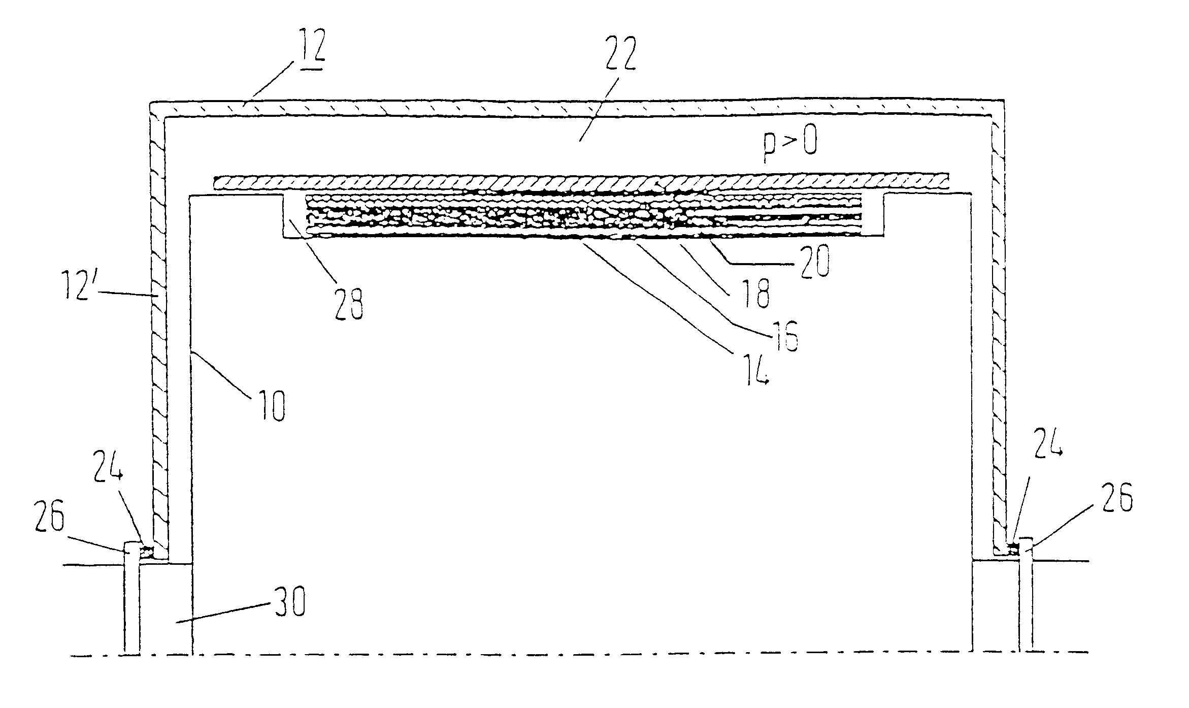
FIGS. 1 through 9 each show a heatable, rotating drying cylinder 10 with an associated, stationary overpressure cap 12 of a drying section of a machine for producing and / or treating of a material web 14. More specifically, the material web 14 can be a paper or cardboard web.

The material web 14 wraps around part of the outer cyl...


PUM


Abstract

An apparatus for at least one of producing and treating a material web is provided including at least one wire; an outer sealing belt, which is wider than said at least one wire, comprising a pair of lateral edge regions; at least one heatable unit, having an outer cylindrical surface, wherein said at least one wire and said outer sealing belt are at least partially wrapped around said at least one heatable unit; an overpressure cap arranged to form a pressure chamber containing a medium under pressure, said medium under pressure exerting a pressure on said at least one heatable unit; and at least one of: (a) a seal formed between said lateral edge regions and said heatable unit; and (b) a seal formed between end faces of said overpressure cap and an opposing wall to seal said pressure chamber from an external environment.

Description

The present application claims priority under 35 U.S.C. .sctn.119 of German Patent Application No. 199 41 334.7, filed on Aug. 31, 1999, the disclosure of which is expressly incorporated by reference herein in its entirety.1 . Field of the InventionThe invention relates to a machine for producing and / or treating a material web, in particular a paper or cardboard web, having at least one heatable unit, such as in particular a pressing roll, a drying cylinder, and / or the like, which is wrapped around part of its outer cylindrical surface by the material web and at least one wire and an outer sealing belt, and having an overpressure cap that subjects the heatable unit to a liquid or gaseous medium under pressure.2. Discussion of Background InformationIt is known to dry material webs on cylinders, between two steel belts (U.S. Pat. No. 4,461,095) or between a heated cylinder and a steel belt or sealing belt (DE 197 23 163 A1). A drying section of the type mentioned initially is describe...

Claims


Application Information

Patent Timeline
IPC IPC(8): D21F5/00D21F5/02D21F5/04F26B13/00F26B13/18F26B13/26F26B13/28F26B13/10
CPCD21F5/004D21F5/02F26B13/28F26B13/18F26B13/26D21F5/044
Inventor HALMSCHLAGER, GUNTERHOLZER, WALTERGLOSER, MANFREDHASLINGER, PETER
Owner VOITH SULZER PAPIERTECHN PATENT
Learn More