Vehicle air conditioner with manually operated operation member

a technology of operation member and air conditioner, which is applied in the direction of vehicle cleaning, gearing, heating types, etc., can solve the problems of incorrect operation of air flow adjustment door, cable assembling error, and bending angle change,

Inactive Publication Date: 2002-06-04
DENSO CORP
View PDF13 Cites 15 Cited by
  • Summary
  • Abstract
  • Description
  • Claims
  • Application Information

AI Technical Summary

Benefits of technology

According to the present invention, in a vehicle air conditioner, an air conditioning unit for adjusting an air state to be blown into the passenger compartment has an adjustment door for adjusting an air flow and a first rotation shaft for rotating the adjustment door. On the other hand, an air-conditioning operation panel has a manually operated operation member and a second rotation shaft rotated by the operation member. The first rotation shaft and the second rotation shaft are disposed on the same direction in such a manner that an operation force of the operation member transmits from the second rotation shaft to the first rotation shaft. Because the axial direction of the first rotation shaft is the same as that of the second rotation shaft, a rotation displacement of the second rotation shaft can be directly transmitted to the first rotation shaft without using a cable. Accordingly, a complex cable connection operation is unnecessary, and production cost can be reduced. Further, it can prevent an operation error of the adjustment door, due to a cable connection error, and it can prevent a door operation force from being increased due to a friction in the cable.
Preferably, the operation member is a rotatably operated rotation member directly connected to the second rotation shaft. Therefore, the second rotation shaft can be directly rotated by the rotation operation of the operation member. The second rotation shaft includes an input rotation shaft disposed to be rotatable by a rotation operation of the operation member, and an output rotation shaft which rotates by a rotation of the input rotation shaft through a gear wheel. Further, the second rotation shaft is disposed in such a manner that an operation force of the operation member is transmitted from the output rotation shaft to the first rotation shaft. Accordingly, the position of the operation member can be set to be offset from the position of the output rotation shaft, and an arrangement position of the air-conditioning operation panel can be readily set.
Preferably, the first rotation shaft has an axial line positioned on the same as that of the second rotation shaft, and the second rotation shaft is directly connected to the first rotation shaft. Therefore, the second rotation shaft can be directly connected to the first rotation shaft by a simple structure. Alternatively, the axial line of the first rotation shaft can be offset from that of the second rotation shaft. In this case, the arrangement position of the air-conditioning operation panel can be readily set.
Preferably, the air-conditioning operation panel is attached to the air conditioning unit to construct an integrated member, and the integrated member is mounted on the vehicle. Because the air-conditioning operation panel and the air conditioning unit are mounted on the vehicle after being integrated beforehand, assembling steps of the air conditioner on the vehicle can be reduced.

Problems solved by technology

In addition, because the cable is constructed by inserting a core line portion into an outer pipe, a cable bending angle may be changed in the cable connection operation, and a cable assemble error may be caused.
Thereby, the air flow adjustment door is not accurately operated, and an air leakage may be caused.
Further, when the cable bending angle is small, a friction between the core line portion and the outer pipe is increased, and a door operation force is increased.

Method used


Image

  • Vehicle air conditioner with manually operated operation member
  • Vehicle air conditioner with manually operated operation member
  • Vehicle air conditioner with manually operated operation member

Examples


first embodiment

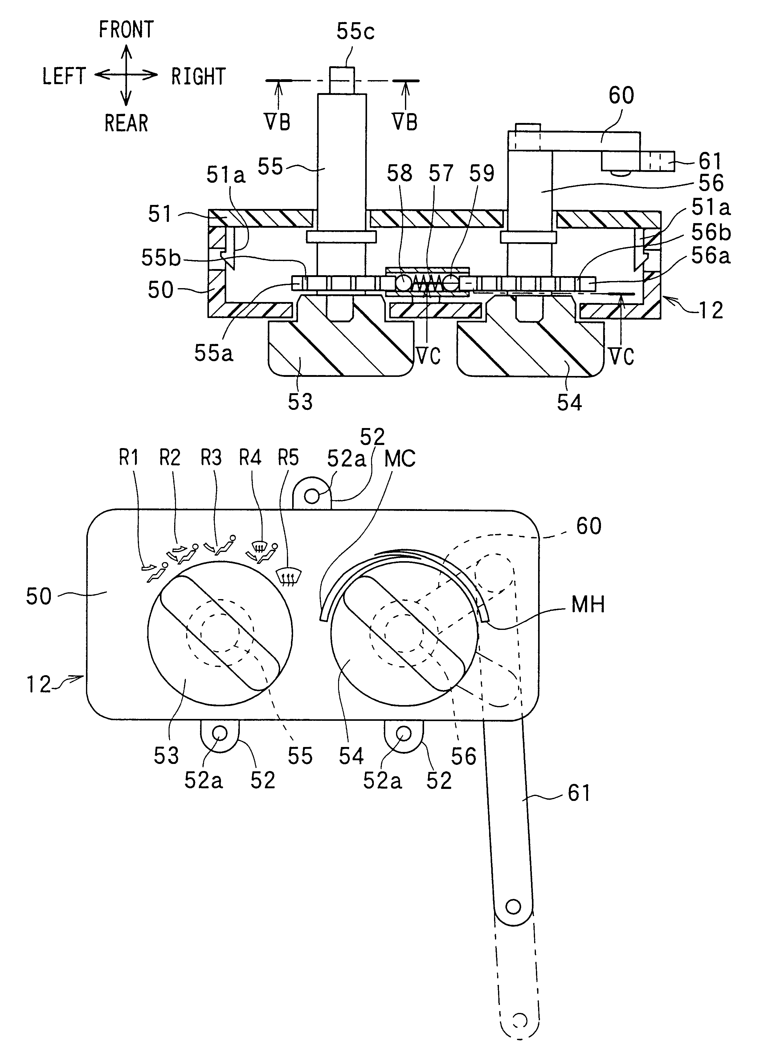
In the present invention, as shown in FIG. 6, by the rotation operation of the operation member 53, the rotary door 28 can be rotated to five air outlet mode positions. That is, when the operation member 53 is rotated to a position R1 in FIG. 6, the rotary door 28 is operated to a face mode position, so that a face mode, where the face opening 34 is fully opened, is set. When the operation member 53 is rotated to a position R2 in FIG. 6, the rotary door 28 is operated to a bi-level mode position, so that a bi-level mode, where both the face opening 34 and the foot opening 35 are opened, is set. When the operation member 53 is rotated to a position R3 in FIG. 6, the rotary door 28 is operated to a foot mode position, so that a foot mode, where the foot opening 35 is fully opened and the defroster opening 33 is slightly opened, is set. When the operation member 53 is rotated to a position R4 in FIG. 6, the rotary door 28 is operated to a foot / defroster mode position, so that a foot / de...

second embodiment

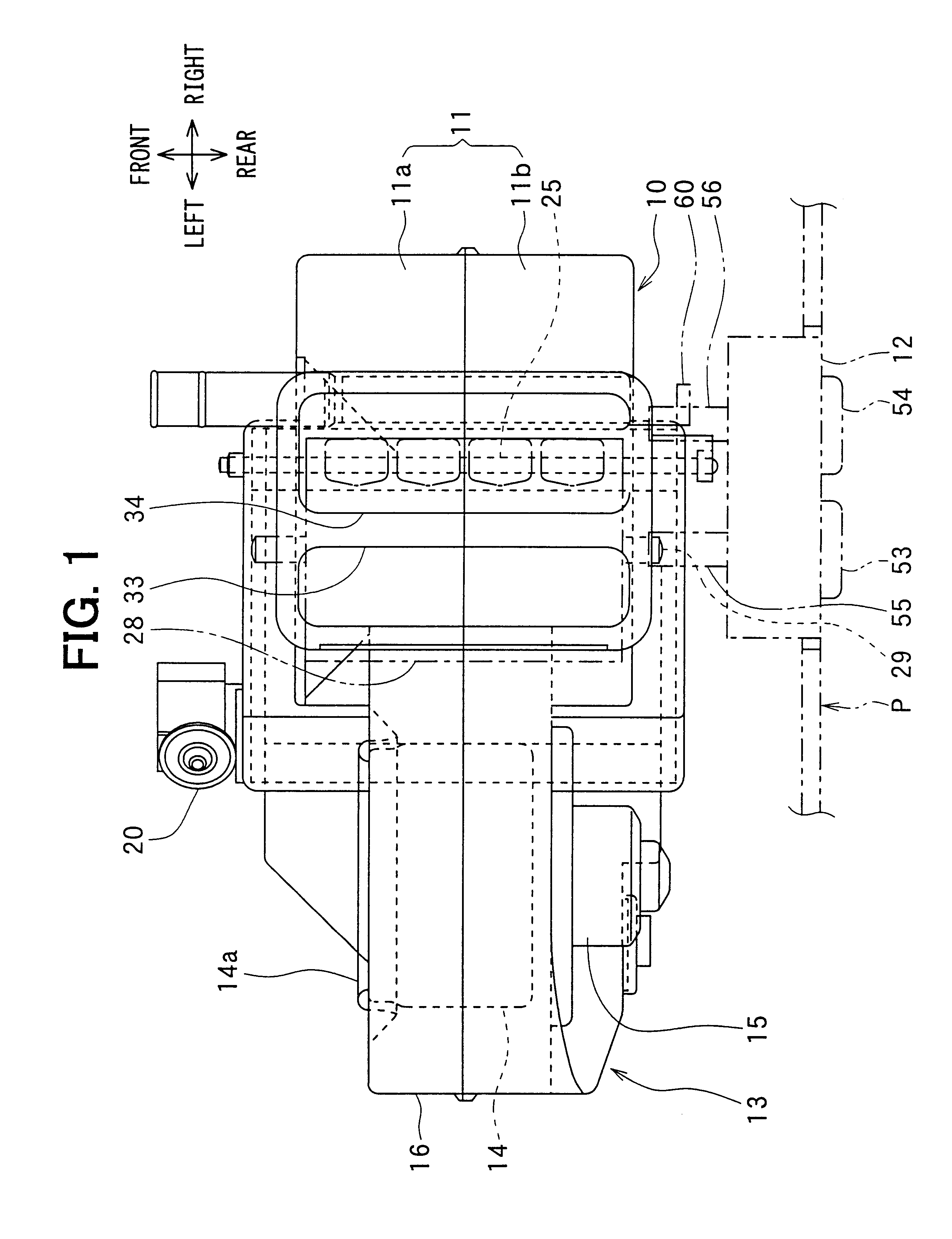
In the present invention, the axial lines of the rotation shafts 55, 56 and the axial lines of the rotation shafts 25, 29 are toward the same direction (e.g., the vehicle front-rear direction). The rotation shaft 55 of the mode switching operation member 53 and the rotation shaft 29 of the mode switching rotary door 28 are connected through a gear wheel, and the rotation shaft 56 of the temperature adjustment operation member 54 and the rotation shaft 25 of the temperature adjustment air mixing door 24 are connected through a gear wheel.

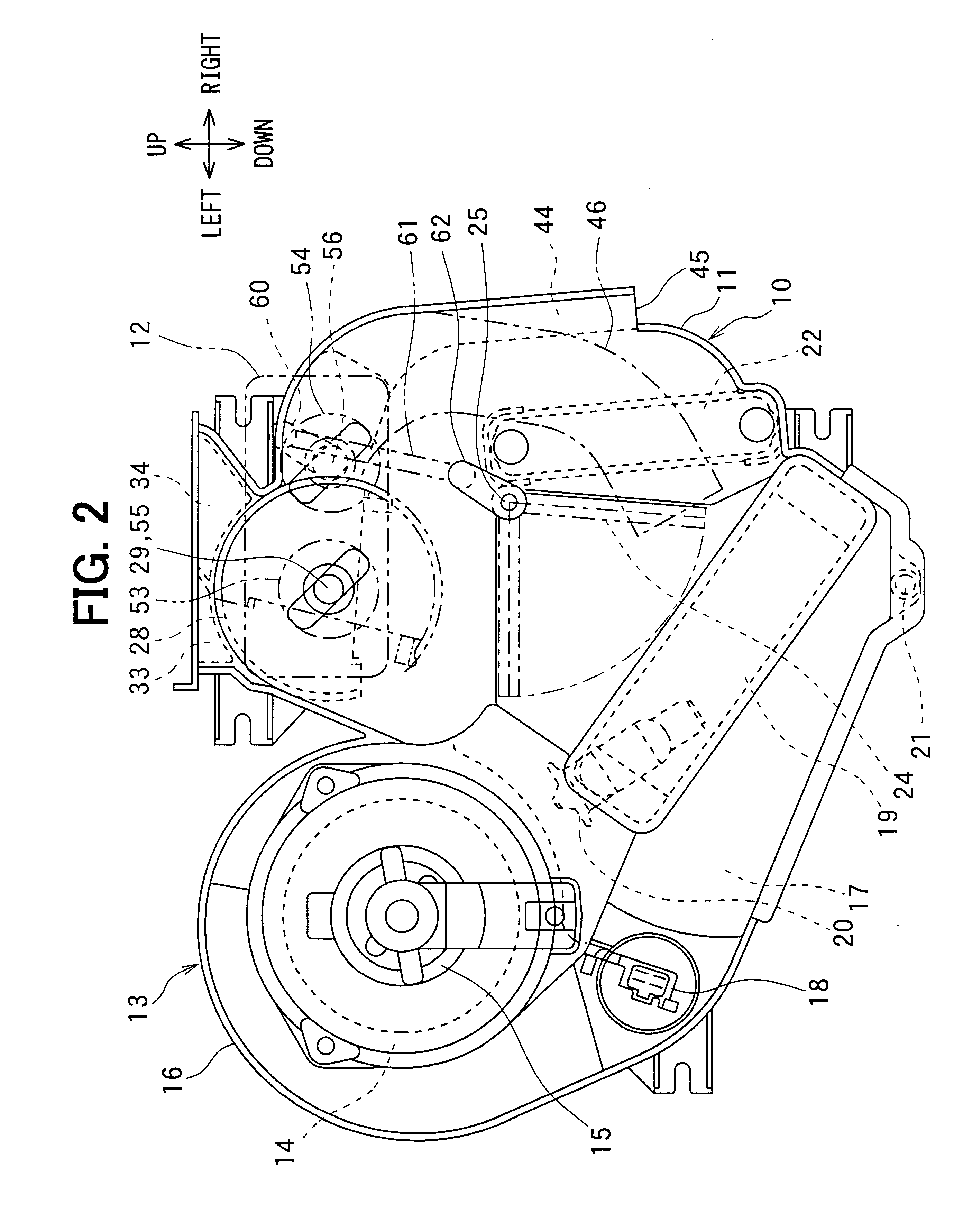
The rotation shaft 29 of the rotary door 28 is positioned relatively at a left upper side, and the rotation shaft 25 of the air mixing door 24 is positioned relatively at a right lower side, as shown in FIG. 2. Accordingly, in the second embodiment, the air-conditioning operation panel 12 is formed into a shape tilted from a left upper side to a right lower side, to correspond to the arrangement of the rotation shaft 29 of the rotary door 28 and the ...

third embodiment

In the third embodiment, the temperature adjustment operation member 54 is disposed at a lower side in the air-conditioning operation member 12, and the axial line (shaft center line) of the rotation shaft 56 of the temperature adjustment operation member 54 is made on the same as the axial line (shaft center line) of the rotation shaft 25 of the air mixing door 24, so that the rotation shaft 56 of the temperature adjustment operation member 54 is directly connected to the rotation shaft 25 of the air mixing door 24. Specifically, as shown in FIG. 11, a small-diameter portion 25a having a non-circular shape such as a D-shape in cross section is formed at a vehicle rear side end of the rotation shaft 25 of the air mixing door 24, and an insertion hole 56d into which the small-diameter portion 25a is inserted is formed at a vehicle front side end of the rotation shaft 56 of the operation member 54. The small-diameter portion 25a of the rotation shaft 25 is press-fitted into the insert...


PUM


Abstract

In a vehicle air conditioner having manually operated operation members of an air-conditioning operation panel, rotation shafts of an air mixing door and a mode switching rotary door are disposed in a vehicle front-rear direction, so that an axial direction of the rotation shafts of the doors is made the same as that of rotation shafts of the operation members of the air-conditioning operation panel. Accordingly, operation force of the operation members can be directly transmitted to the rotation shafts of the doors by a simple structure.

Description

This application is related to Japanese Patent Application No. 2000-241534 filed on Aug. 9, 2000, the contents of which are hereby incorporated by reference.1. Field of the InventionThe present invention relates to a manual operation mechanism for an air flow adjustment door disposed in an air conditioning unit of a vehicle air conditioner.2. Description of Related ArtIn a conventional vehicle air conditioner described in JP-Y2-7-40402, a rotation shaft of an air flow adjustment door is connected to an operation member of an air-conditioning operation panel through a cable, so that the air flow adjustment door is operated through the cable by manually operating the operation member of the air-conditioning operation panel. Because a manual operation force of the operation member of the air-conditioning operation panel is transmitted to the air flow adjustment door through the cable, a cable connection operation is need to be performed in a small space after an air conditioning unit i...

Claims


Application Information

Patent Timeline
Patent Type & Authority Patents(United States)
IPC IPC(8): B60H1/00
CPCB60H1/0065B60H1/00857Y10T74/18816
Inventor SHIBATA, KAZUJIYOSHIDA, YOSHIO
Owner DENSO CORP
Why Eureka
Try Eureka