Valve characteristic control apparatus of internal combustion engine and methods of controlling valve characteristics

a valve characteristic and control apparatus technology, applied in the direction of electric control, machines/engines, output power, etc., can solve the problems of difficult fault diagnosis regarding the valve timing-varying mechanism, inability to simply apply the diagnostic technique employed by the aforementioned apparatus, and difficulty in identifying which mechanism has an abnormality

Inactive Publication Date: 2002-06-18
TOYOTA JIDOSHA KK
View PDF6 Cites 39 Cited by
  • Summary
  • Abstract
  • Description
  • Claims
  • Application Information

AI Technical Summary

Benefits of technology

In accordance with a third aspect of the invention, a valve characteristic control apparatus of an internal combustion engine includes a camshaft provided with a three-dimensional cam having a cam profile that continuously changes in a direction of an axis of the cam, a valve lift-varying mechanism that allows an amount of valve lift of an engine valve to be varied in accordance with a displaced position of the camshaft in the direction of the axis of the cam, a sensor that detects an actual amount of valve lift and a controller that receives a signal from the sensor and diagnoses that there is an abnormality of the valve lift-varying mechanism, provided that a deviation between an actually detected amount of valve lift and a target amount of valve lift of the engine valve is greater than a predetermined value and that there is no abnormality in a retainment control system while in a state where an instruction to retain the amount of valve lift is outputted is present.
In this construction, it is possible to precisely diagnose whether the valve lift-varying mechanism has any one of various abnormalities, similarly to the diagnostic means in the first to third aspects. Furthermore, this construction greatly reduces the possibility of a failure in diagnosis regarding the various abnormalities.

Problems solved by technology

Therefore, for the diagnosis regarding the presence / absence of a failure of the mechanism, the diagnostic technique employed by the aforementioned apparatus cannot be simply applied.
That is, for example, in a valve characteristic control apparatus employing a cam angle sensor, the fault diagnosis regarding the valve timing-varying mechanism becomes difficult in a relatively early period as the camshaft is displaced by the valve lift-varying mechanism.
Furthermore, since both mechanisms use continuous values for their respective variable controls, it is not easy to identify which one of the mechanisms has an abnormality if any abnormality occurs.
However, with regard to the continuous displacement control of the camshaft in the direction of the axis, the target amount of valve lift and the actually detected amount of valve lift are not always equal, due to a response delay in the control.
Furthermore, this construction greatly reduces the possibility of a failure in diagnosis regarding the various abnormalities.
One of the abnormalities related to the valve lift-varying mechanism is an operation failure caused by a metal chip or the like trapped in the mechanism, for example, in a hydraulic oil supply system, that is, a drive system.
Furthermore, in the aforementioned aspects, the controller may cause the execution of a fail-safe operation if the mechanism diagnosed as having an abnormality by the controller is the valve lift-varying mechanism.
Furthermore, the fail-safe operation is at least one of increasing a fuel supplied to the engine, prohibiting a learning regarding an idle revolution speed control, prohibiting a learning regarding an air-fuel ratio feedback control, expanding a fuel-cut operation region, and upwardly shifting a fuel-cut return revolution speed.

Method used


Image

  • Valve characteristic control apparatus of internal combustion engine and methods of controlling valve characteristics
  • Valve characteristic control apparatus of internal combustion engine and methods of controlling valve characteristics
  • Valve characteristic control apparatus of internal combustion engine and methods of controlling valve characteristics

Examples


Embodiment Construction

)

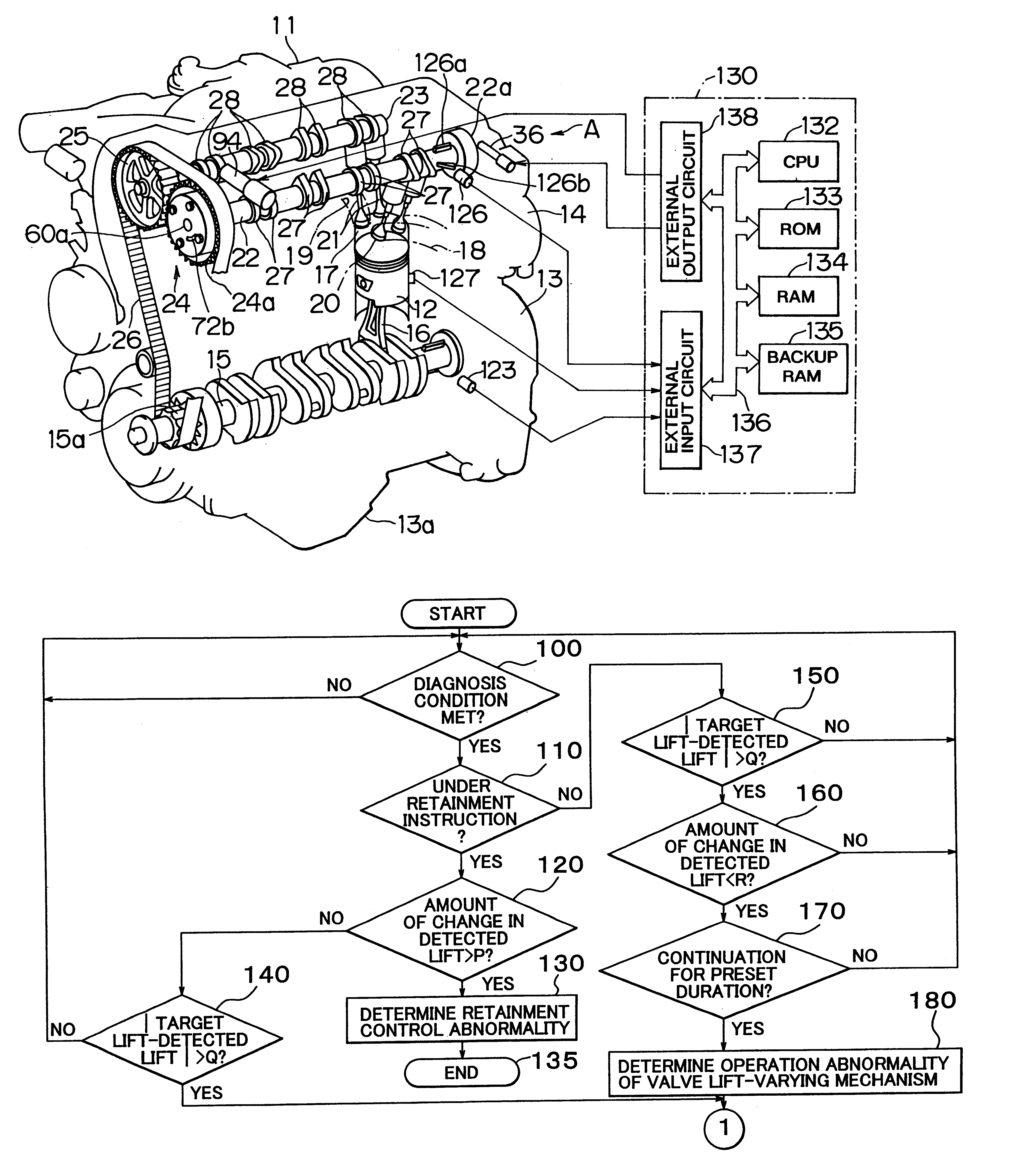
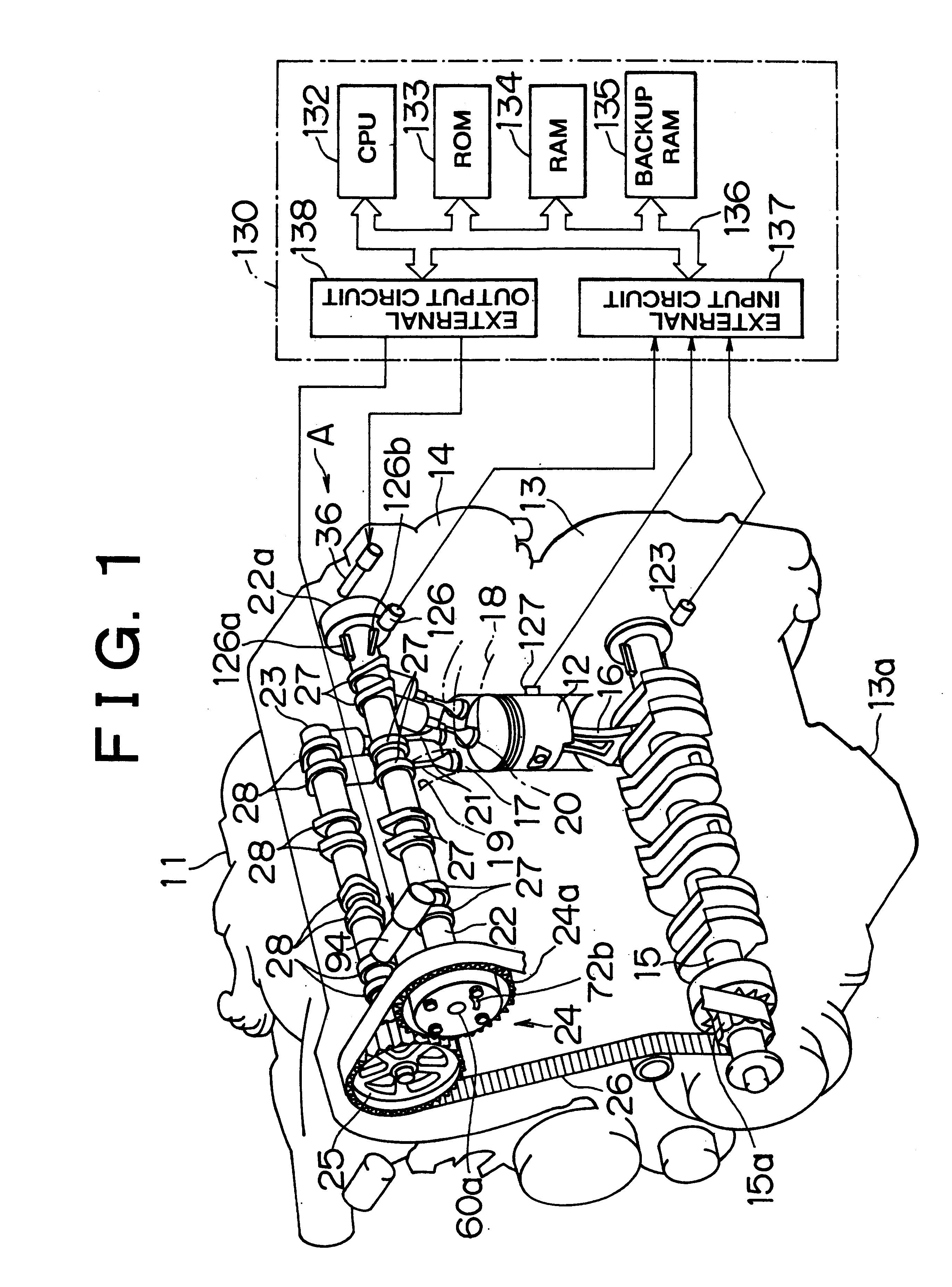
An embodiment in which the valve characteristic control apparatus of an internal combustion engine of the invention is embodied will be described hereinafter with reference to FIGS. 1 to 8.

FIG. 1 shows an in-line four-cylinder gasoline engine (hereinafter "engine") 11 for installation in a vehicle as an internal combustion engine. The engine 11 has a cylinder block 13 in which reciprocating pistons 12 are provided, an oil pan 13a provided below the cylinder block 13, and a cylinder head 14 provided above the cylinder block 13.

A crankshaft 15, which is an output shaft of the engine 11 and is rotatably supported in a lower portion of the engine 11. The pistons 12 are connected to the crankshaft 15 via connecting rods 16. Reciprocating movements of the pistons 12 are converted into a rotational movement of the crankshaft 15 by the connecting rods 16. A combustion chamber 17 is formed above each piston 12. The combustion chambers 17 are connected with intake passages 18 and exhaust pas...


PUM


Abstract

A camshaft provided with three-dimensional cams is connected at its one end to a valve lift-varying actuator. By the valve lift-varying actuator or displacing the camshaft in the directions of an axis of the camshaft, the lift characteristic of intake valves set by the three-dimensional cams is variably controlled to a target amount of valve lift. The valve lift characteristic related to this control is detected as a detected amount of valve lift by a reference-purposed detected portion and a cam angle sensor. An apparatus and a method diagnoses abnormalities in the valve lift-varying actuator by, for example, evaluating whether the amount of change in the detected amount of valve lift is at most a predetermined value and the absolute value of a difference between the detected amount of valve lift and the target amount of valve lift is greater than a predetermined value.

Description

INCORPORATION BY REFERENCEThe disclosure of Japanese Patent Application No. 2000-065449 filed on Mar. 9, 2000 including the specification, drawings and abstract is incorporated herein by reference in its entirety.1. Field of InventionThe invention relates to methods and a valve characteristic control apparatus of an internal combustion engine for variably controlling the valve characteristic of an engine valve in accordance with the operation state of the engine.2. Description of the Related ArtAs a valve characteristic control apparatus, an apparatus described in Japanese Patent Application Laid-Open No. 8-177434, as for example, is known. This apparatus includes a valve lift-varying mechanism that allows variation of the amount of valve lift of an engine valve, and a valve timing-varying mechanism that allows variation of the valve timing. If either one of the varying mechanisms has a fault, the following control is performed. That is, with regard to the valve lift-varying mechani...

Claims


Application Information

Patent Timeline
Patent Type & Authority Patents(United States)
IPC IPC(8): F01L13/00F02D41/22F01L1/344F02D41/00F01L1/34F01L1/46F02D13/02
CPCF01L1/34406F01L1/3442F01L13/0042F02D13/0207F02D13/0226F02D41/221F01L1/024F01L2001/0537F01L2001/34469Y02T10/40F01L2800/12F02D2041/001Y02T10/18F01L2800/00Y02T10/12F02D13/02
Inventor MIKAME, KAZUHISA
Owner TOYOTA JIDOSHA KK
Why Eureka
Try Eureka