Method of producing individual plasmas in order to create a uniform plasma for a work surface, and apparatus for producing such a plasma

a technology of individual plasmas and work surfaces, which is applied in the direction of plasma welding apparatus, plasma technique, manufacturing tools, etc., can solve the problems of unsuitable plasma for most industrial applications, unreliable plasma production, and inability to produce uniform plasma along the magnet,

Inactive Publication Date: 2002-06-18
H E F
View PDF9 Cites 94 Cited by
  • Summary
  • Abstract
  • Description
  • Claims
  • Application Information

AI Technical Summary

Benefits of technology

The object of the invention is thus to remedy the drawbacks of the prior art by proposing a method that make

Problems solved by technology

The major drawback of the technique described in that patent lies in the fact that the zone in which microwave energy propagates and the resonance zone in which the microwave energy is absorbed are superposed.
The resulting plasma presents density that is not uniform along the exciter, and as a result such a plasma appears to be unsuitable for most industrial applications.
In that case also, the microwave propagates mainly in the electron cyclotron resonance zone and are therefore subjected to a high level of attenuation, which leads to a plasma being produced that is not uniform along the magnet.
Nevertheless, the techniques described in those patents No. 91 00 894 and 94 13 499 where microwave propagation takes place in the form of standing waves suffers from the difficulty of obtaining constant amplitude, in particular over a relatively long length of the microwave applicator.
An analysis of the various prior art techniques leads to non-uniformities being ob

Method used


Image

  • Method of producing individual plasmas in order to create a uniform plasma for a work surface, and apparatus for producing such a plasma
  • Method of producing individual plasmas in order to create a uniform plasma for a work surface, and apparatus for producing such a plasma
  • Method of producing individual plasmas in order to create a uniform plasma for a work surface, and apparatus for producing such a plasma

Examples


Embodiment Construction

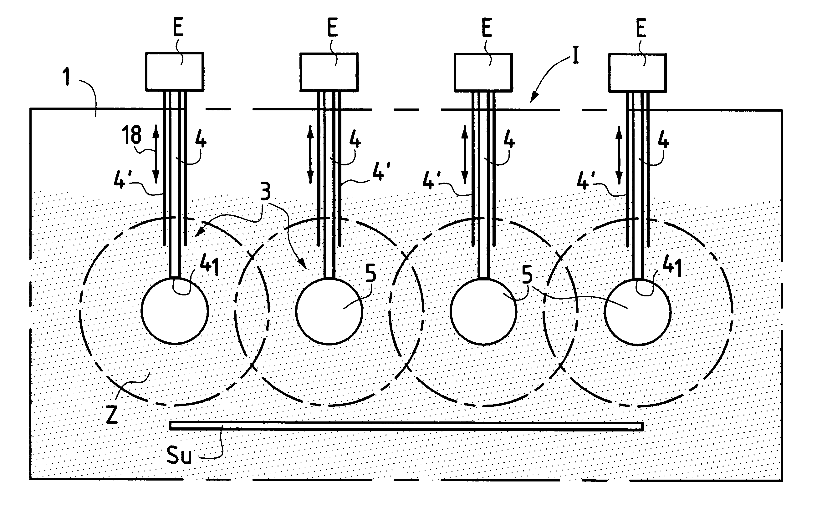
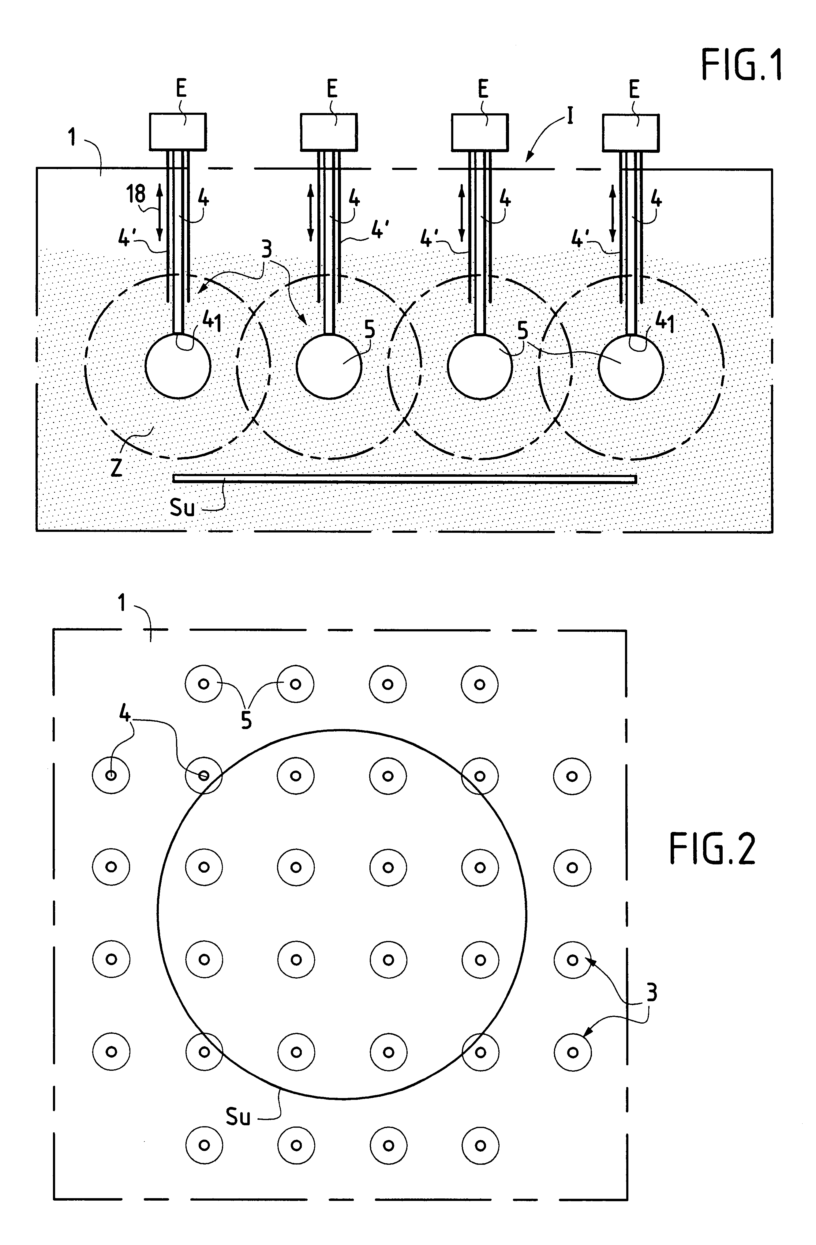
By way of example, FIGS. 1 and 2 show apparatus I for producing a plasma relative to a work surface S.sub.u ("work" in a broad sense), which can be constituted, for example, by a surface that is suitable for receiving various surface treatments. In conventional manner, the apparatus I comprises a sealed enclosure 1 represented diagrammatically and fitted with devices for admitting gas and for pumping gas out, not shown but known per se, that enable the pressure of the gas that is to be ionized to be maintained at a desired value which, for example, can be about 10.sup.-3 to a few tens of Pascals, depending on the nature of the gas and the excitation frequency.

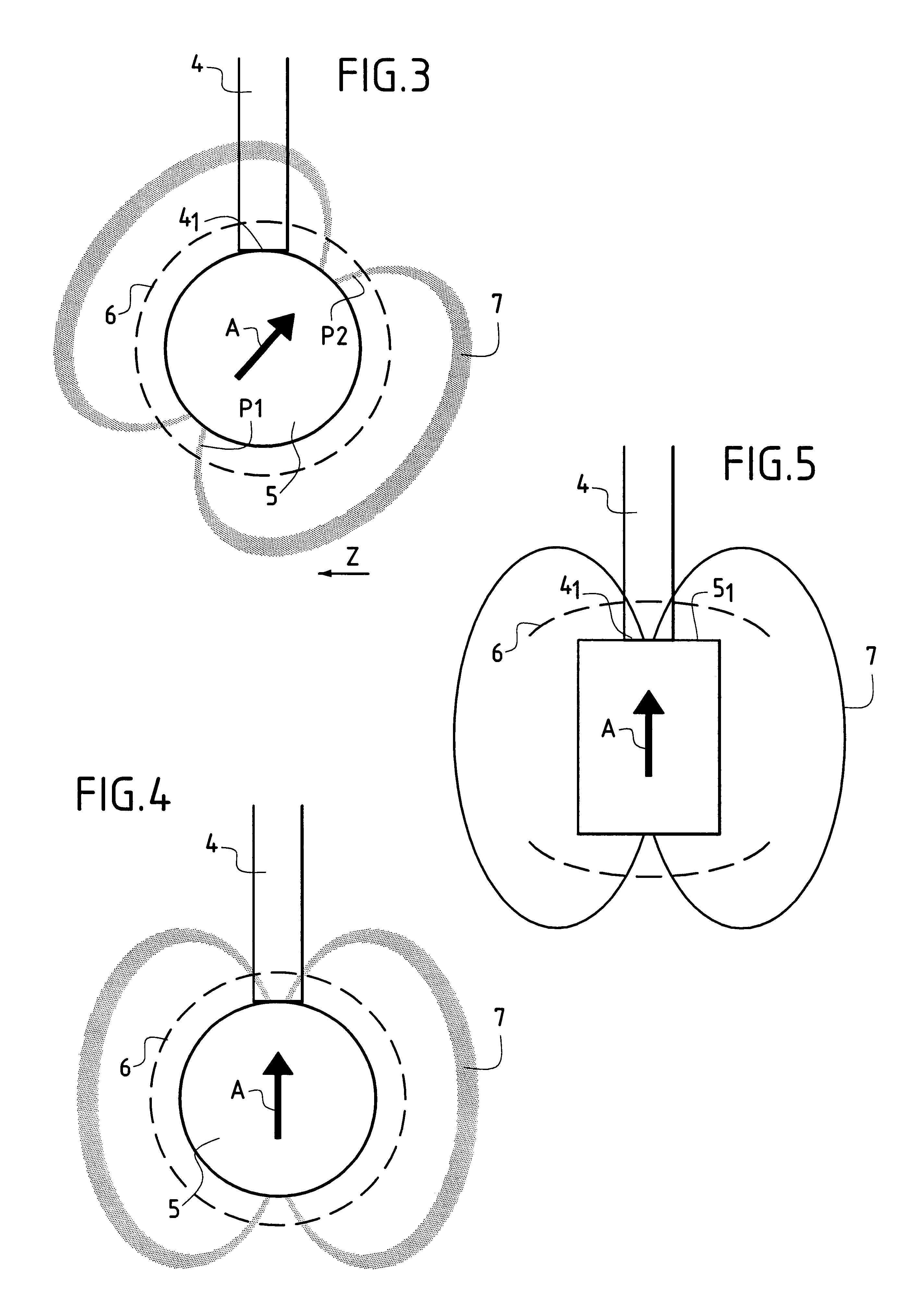
In accordance with the invention, the plasma production apparatus I has a series of individual plasma excitation devices 3 spaced apart from one another and located in the proximity of the work surface S.sub.u so as to operate together to create a plasma that is uniform for said work surface S.sub.u. In the invention, each indi...


PUM

PropertyMeasurementUnit
Diameteraaaaaaaaaa
Magnetic fieldaaaaaaaaaa
Distanceaaaaaaaaaa

Abstract

The invention provides apparatus having a series of individual plasma excitation devices each constituted by a wire applicator of microwave energy, having one end connected to a source for producing microwave energy and having an opposite end fitted with at least one magnetic dipole for creating at least one surface having a magnetic field that is constant and of intensity corresponding to electron cyclotron resonance, the dipole being mounted at the end of the microwave applicator in such a manner as to ensure that electrons accelerated to electron cyclotron resonance oscillate between the poles so as to create a plasma diffusion zone situated on the side of the dipole that is remote from the end of the applicator, the individual excitation devices being distributed relative to one another and in proximity with the work surface so as to create together a plasma that is uniform for the work surface.

Description

The present invention relates to the general technical field of producing a low-pressure plasma excited by microwave energy in the electron cyclotron resonance range.The invention relates to all applications requiring controllable plasma uniformity over large areas that can be plane or curved in shape.The present invention relates to a wide variety of applications, such as surface treatments, e.g. etching, deposition, chemical or thermochemical treatment, spraying, cleaning, disinfection, decontamination, or producing ion beams obtained by extracting plasma.In the technical field of exciting a plasma to electron cyclotron resonance, resonance is obtained when the frequency of gyration of an electron in a static or quasi-static magnetic field is equal to the frequency of the applied accelerating electric field. This resonance is obtained for a magnetic field B at an excitation frequency f which are associated by the following relationship:B=2.pi.mf / ewhere m and e are the mass and the...

Claims


Application Information

Patent Timeline
IPC IPC(8): H05H1/46H01L21/205H01L21/302H01L21/3065
CPCH01J37/3222H05H1/46H01J37/32678
Inventor LAGARDE, THIERRYPELLETIER, JACQUES
Owner H E F
Why Eureka
Try Eureka