Blow molded headliner

a blow molding and headliner technology, applied in the direction of pedestrian/occupant safety arrangements, vehicular safety arrangements, other domestic objects, etc., to achieve the effect of reducing noise levels and improving the ability of the cavity to absorb the impact force of the passenger head

Inactive Publication Date: 2002-06-25
COLLINS & ALKMAN PROUCTS
View PDF3 Cites 70 Cited by
  • Summary
  • Abstract
  • Description
  • Claims
  • Application Information

AI Technical Summary

Benefits of technology

According to another aspect of the invention, the cavity comprises an air duct and the headliner includes an air inlet opening positioned to receive air from a vehicle air handling system. An air outlet opening is spaced from the air inlet opening and disposed in an underside surface of the headliner assembly to direct air from the vehicle air handling system into the passenger compartment. The air duct extends between and connects the air inlet opening and the air outlet opening to provide gaseous communication between the air inlet opening and the air outlet opening. Because the air duct is formed into the headliner substrate, the headliner assembly includes fewer parts and its fabrication is greatly simplified.
According to another aspect of the invention, foam is disposed within the cavity. The cavity may include an inner wall that envelops the foam. The foam may be energy-absorbing foam to enhance the ability of the cavity to absorb passenger head impact forces. The foam may be an acoustic energy-absorbing foam to reduce noise levels within the passenger compartment.

Problems solved by technology

However, neither the Van Order et al. patent nor the Strapazzini patent disclose a headliner or a method for making a headliner with structures that can direct airflow in or out of a vehicle interior and / or support energy absorbing materials.

Method used


Image

  • Blow molded headliner
  • Blow molded headliner
  • Blow molded headliner

Examples


Embodiment Construction

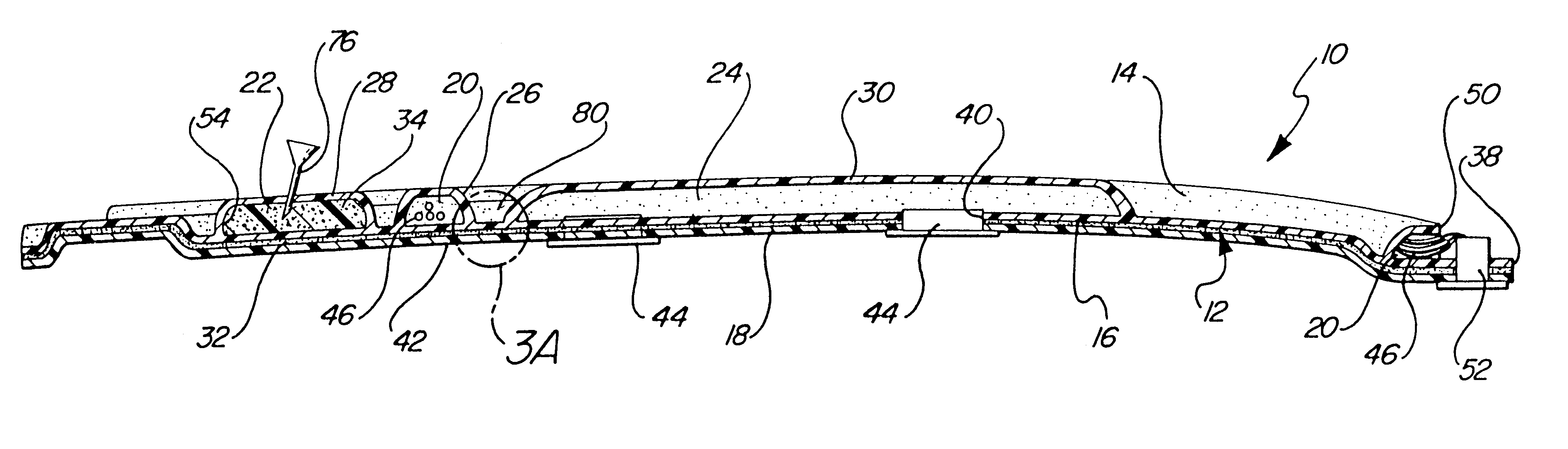
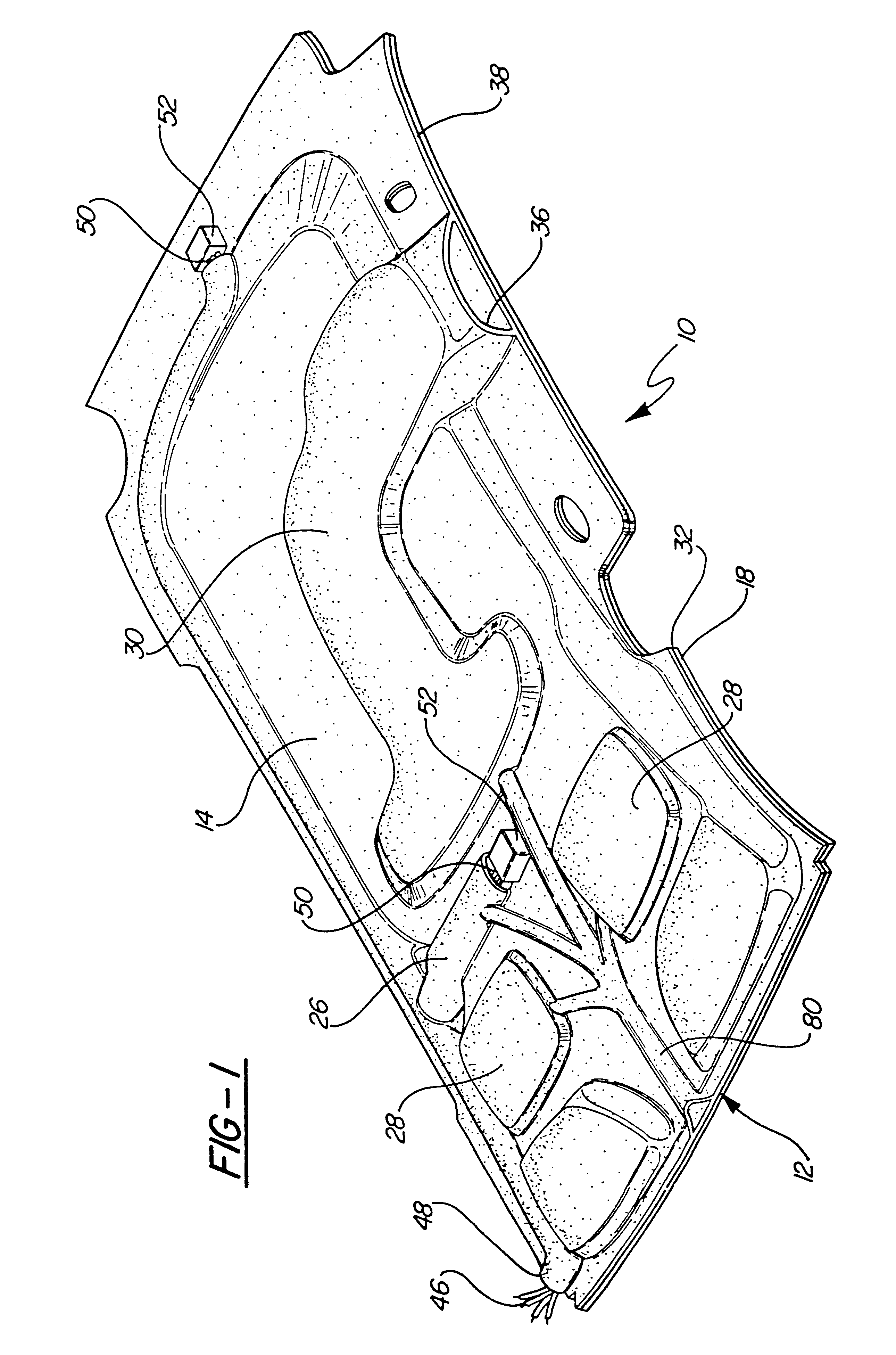
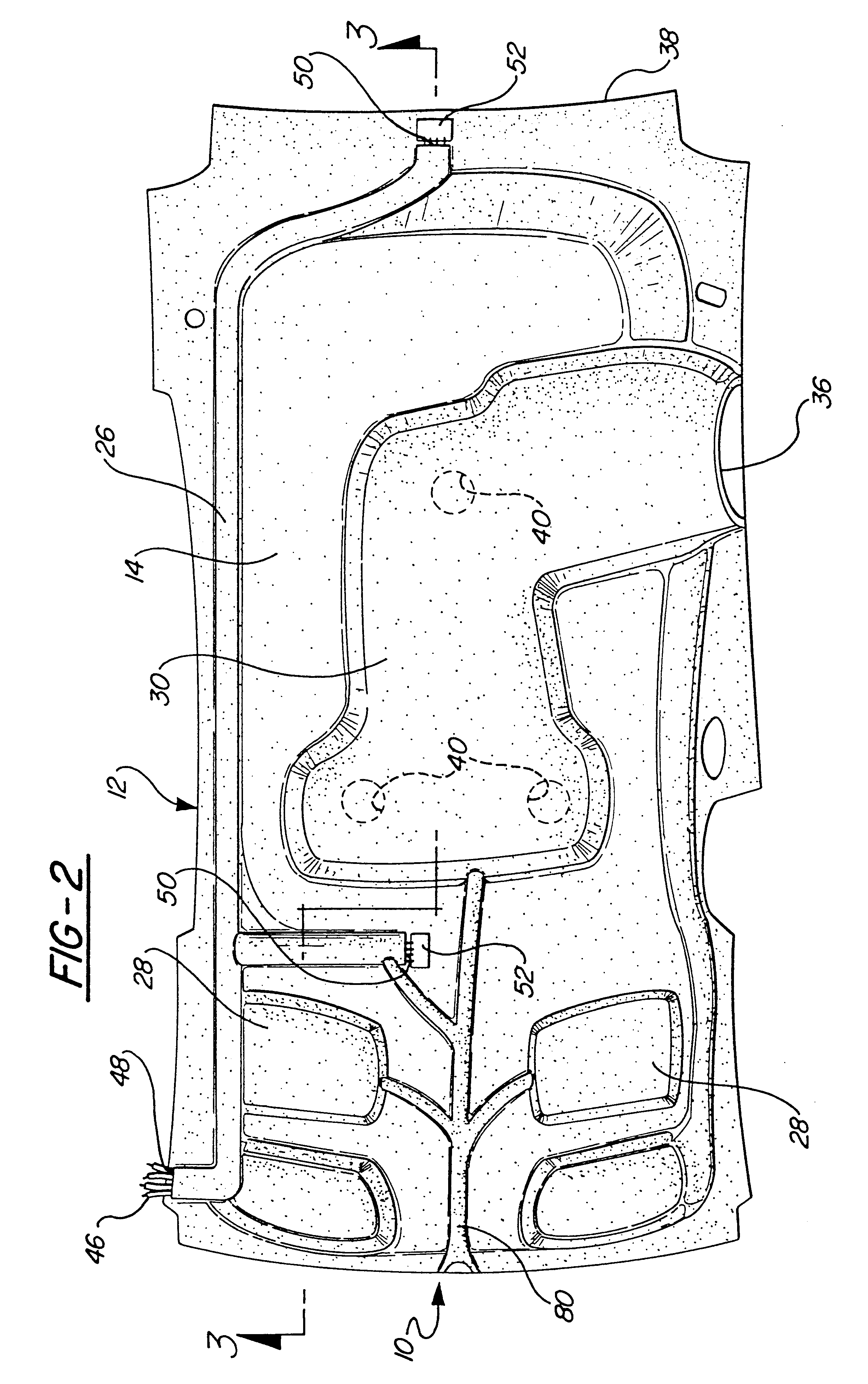
A headliner assembly for lining the roof of the passenger compartment of a vehicle is generally shown at 10 in FIGS. 1-3. The headliner assembly 10 includes a unitary substrate, generally indicated at 12 in FIGS. 1-3, that is configured to mount to a vehicle in a position generally covering a lower surface of a passenger compartment roof (not shown). The substrate 12 includes an upper substrate surface shown at 14 in FIGS. 1-3 and a lower substrate surface shown at 16 in FIG. 3. The lower substrate surface 16 is disposed opposite the upper substrate surface 14. The substrate 12 may be made of any suitable moldable material to include various plastics or fiberglass reinforced polyester resin.

A decorative cover, shown at 18 in FIG. 3, is supported on the lower substrate surface 16. The decorative cover 18 may be in the form of a fabric or solid layer of any suitable material.

Cavities, shown at 20, 22 and 24 in FIG. 3 are formed into the substrate 12 between the upper substrate surface...


PUM

PropertyMeasurementUnit
sound absorptionaaaaaaaaaa
energy absorptionaaaaaaaaaa
softaaaaaaaaaa

Abstract

An automotive headliner assembly includes a substrate that is configured to mount to a vehicle in a position generally covering a lower surface of a passenger compartment roof. Cavities are formed into the substrate between the upper substrate surface and the lower substrate surface to provide receptacles for electrical wiring, fiber optic cabling, EA foam and the like or to form a duct for directing air flow. Each of the cavities is integrally formed in the substrate. A foam layer is adhered to a lower surface of the substrate and the decorative cover is adhered to a lower surface of the foam layer. The headliner is constructed by first extruding molten parison into a blow mold shaped to complement the desired exterior contours of the headliner substrate to be formed. The cavities are then formed in the molten parison by inserting at least one blow pin into the parison and injecting pressurized gas. For those cavities that are configured to hold energy-absorbing foam, foam is provided within each such cavity by inserting a nozzle into the cavities and filling the cavities with the foam.

Description

This invention relates generally to an automotive headliner having an integral cavity and a method for making such a headliner.INVENTION BACKGROUNDInside vehicle roof constructions sometimes include laminated headliners. Such headliners are used in many types of vehicles including passenger cars, vans, buses, trucks, trains and airplanes. Headliners are incorporated into vehicle roof constructions for a variety of reasons including aesthetics, sound absorption, energy absorption, and concealment of electrical wiring harnesses and air vents.Materials currently used in headliner construction include particleboard, fiberboard, plastic board, scrim, fabric, plastic, various foams and resin-bonded chopped glass fiber. In some headliners, layers of these materials are joined together into a single laminate structure using lay-up-molding techniques. For example, some headliners are constructed using glass reinforced polyester resin laminated to a rigid urethane foam layer and covered by a ...

Claims


Application Information

Patent Timeline
Patent Type & Authority Patents(United States)
IPC IPC(8): B60K37/00B60R21/20B60R13/02B60R11/02B60R11/00B60R13/08B60R21/215B60R21/216B60R21/2165
CPCB60K37/00B29C44/18B60R13/02B60R13/0225B60R13/0262B60R21/216B60R21/2165B60R11/02B60R11/0205B60R11/0211B60R11/0229B60R11/0252B60R13/0275B60R13/0815B60R13/0846B60R2011/0005B60R2011/0007B60R2011/0043B60R2011/0045B60R2011/0082B60R2011/0092B60R2011/0094B60R2011/0096B60R2011/0276B60R2013/0287B60R2021/21537B29C44/14
Inventor WANDYEZ, GLORIA D.
Owner COLLINS & ALKMAN PROUCTS
Why Eureka
Try Eureka