Plasma etching of silicon using a chlorine chemistry augmented with sulfur dioxide

Inactive Publication Date: 2002-07-02
APPLIED MATERIALS INC
View PDF10 Cites 5 Cited by
  • Summary
  • Abstract
  • Description
  • Claims
  • Application Information

AI Technical Summary

Benefits of technology

To facilitate understanding, identical reference numerals have been used, wh

Problems solved by technology

However, since these conductive lines can introduce unwanted electrical signals in the semiconductor substrate during operation of these devices, the devices are separated from each other by some means of isolation.
A selectivity of less than 1.0 is considered

Method used


Image

  • Plasma etching of silicon using a chlorine chemistry augmented with sulfur dioxide
  • Plasma etching of silicon using a chlorine chemistry augmented with sulfur dioxide
  • Plasma etching of silicon using a chlorine chemistry augmented with sulfur dioxide

Examples


Embodiment Construction

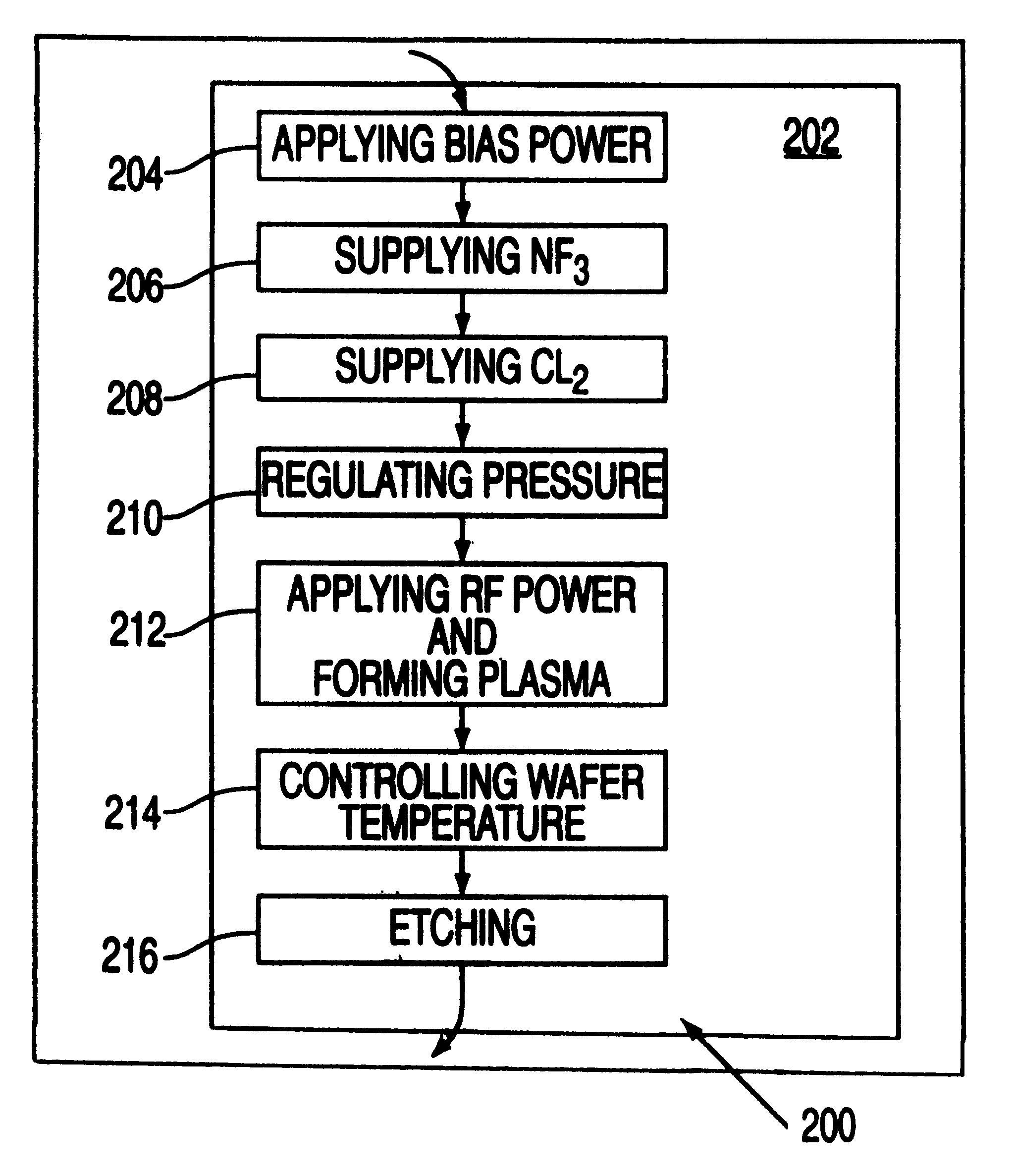
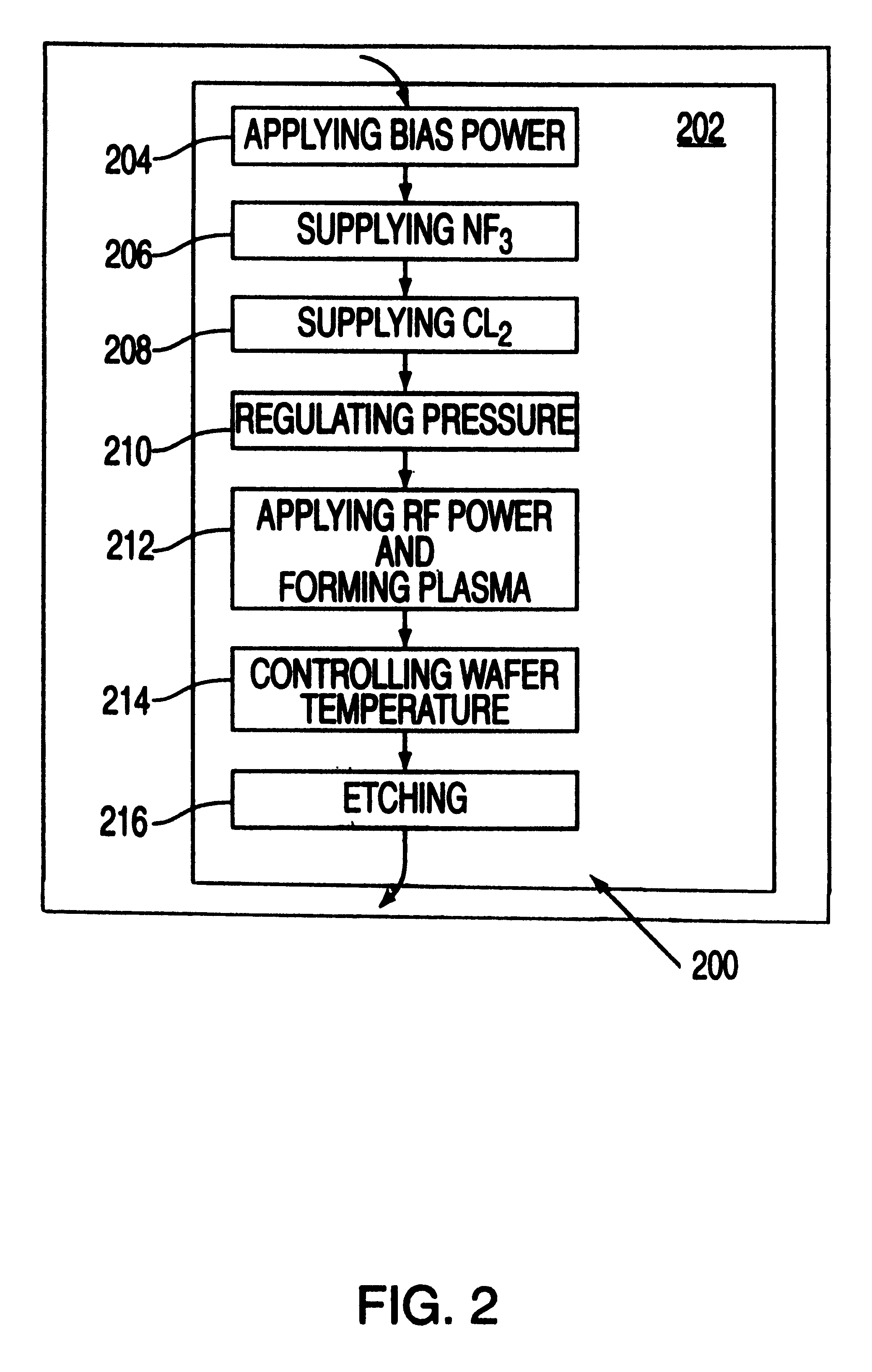
The present invention is a method of silicon etching using a plasma generated from a gas (or gas mixture) comprising gases containing chlorine (Cl.sub.2, HCl and the like) and sulfur dioxide (SO.sub.2). The etch process of the present invention can be reduced to practice in a Silicon Decoupled Plasma Source (DPS) Centura.RTM. etch system available from Applied Materials, Inc. of Santa Clara, Calif.

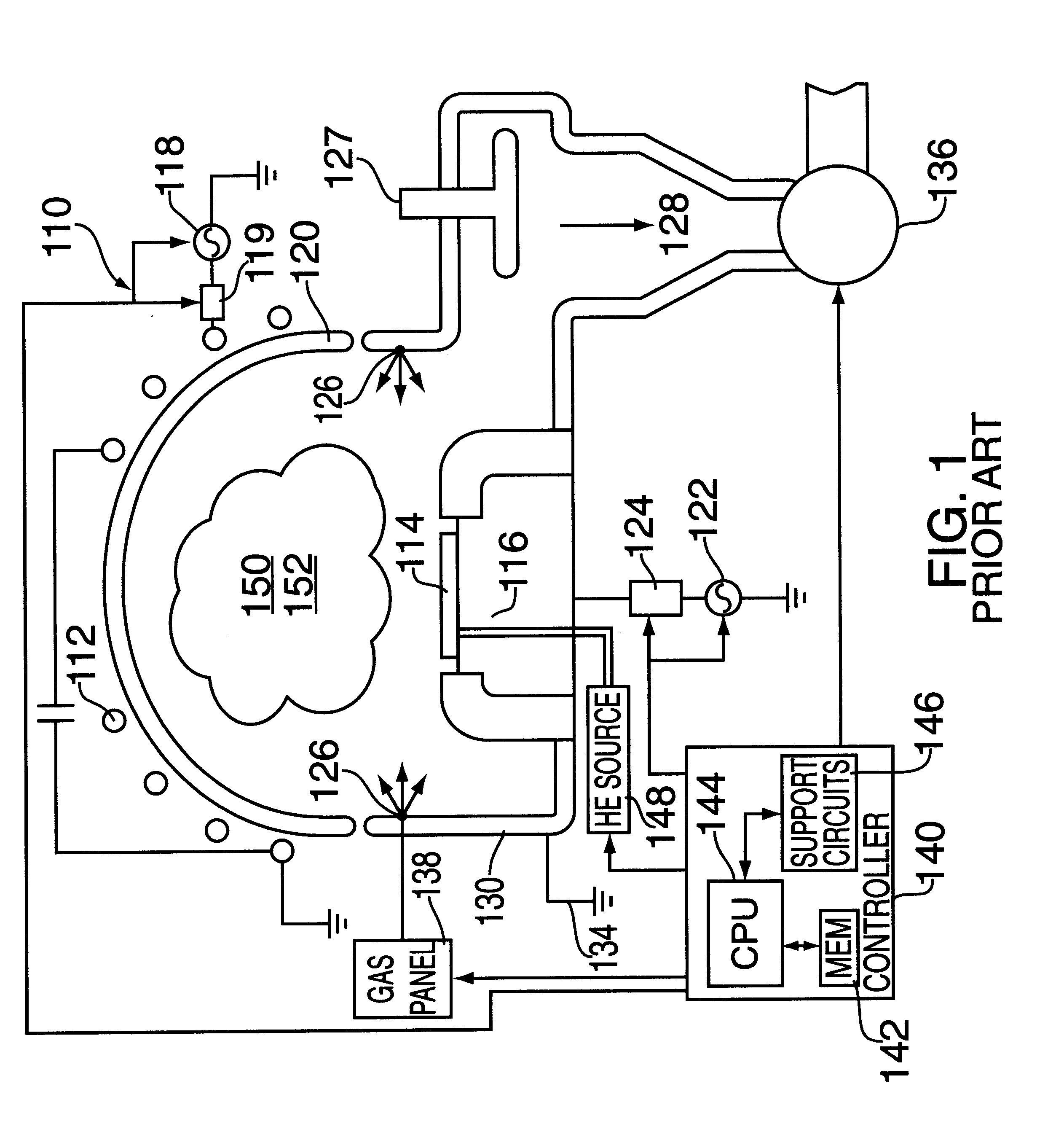
FIG. 1 depicts a schematic diagram of the DPS etch process chamber 110, that comprises at least one inductive coil antenna segment 112, positioned exterior to a dielectric, dome-shaped ceiling 120 (referred to herein as the dome 120). The antenna segment 112 is coupled to a radio-frequency (RF) source 118 (that is generally capable of producing an RF signal having a tunable frequency of about 12.56 MHz). The RF source 118 is coupled to the antenna 112 through a matching network 119. Process chamber 110 also includes a substrate support pedestal (cathode) 116 that is coupled to a second RF ...


PUM

PropertyMeasurementUnit
Temperatureaaaaaaaaaa
Pressureaaaaaaaaaa

Abstract

A method of etching silicon using a chlorine and sulfur dioxide gas chemistry. An embodiment of the method is accomplished using a 20 to 300 sccm of chlorine and 2 to 100 sccm of sulfur dioxide, regulated to a total chamber pressure of 2-100 mTorr.

Description

BACKGROUND OF THE DISCLOSURE1. Field of InventionThe present invention relates generally to a method of dry etching semiconductor wafers. More specifically, the invention relates to a method of etching silicon using a gas mixture comprising chlorine with sulfur dioxide.2. Description of the Background ArtDuring state-of-the-art semiconductor processing of semiconductor devices, many devices are made in a single substrate, such as a silicon wafer. These devices are connected to each other by means of conductive lines. However, since these conductive lines can introduce unwanted electrical signals in the semiconductor substrate during operation of these devices, the devices are separated from each other by some means of isolation. The usual means of isolation is to etch trenches in the substrate between the devices that can be filled with a dielectric material, such as silicon dioxide.Such trenches, since they are later filled with a dielectric material, should have sidewalls that are...

Claims


Application Information

Patent Timeline
IPC IPC(8): G06F19/00H01L21/302H01L21/02H01L21/3065
CPCH01J37/321H01J37/32935H01L21/3065
Inventor NALLAN, PADMAPANI C.KUMAR, AJAYCHINN, JEFFREY D.
Owner APPLIED MATERIALS INC
Why Eureka
Try Eureka