Hand-held tool with a linear oscillating drive

a linear oscillating drive and hand-held tool technology, which is applied in the direction of portable power-driven tools, percussive tools, metal sawing apparatus, etc., can solve the problems of frequency dependence and increase the length of the structure of the vibration damper, and achieve the effect of short external diameter, efficient vibration damping, and small external diameter

Inactive Publication Date: 2002-07-09
BIAX MASCHEN
View PDF10 Cites 34 Cited by
  • Summary
  • Abstract
  • Description
  • Claims
  • Application Information

AI Technical Summary

Benefits of technology

The invention is based on the object of providing a handtool of the type described in the introduction which allows efficient vibration damping combined with a short structure and a small external diameter.

Problems solved by technology

However, this vibration damper increases the length of the structure and is frequency-dependent.

Method used


Image

  • Hand-held tool with a linear oscillating drive
  • Hand-held tool with a linear oscillating drive

Examples


Embodiment Construction

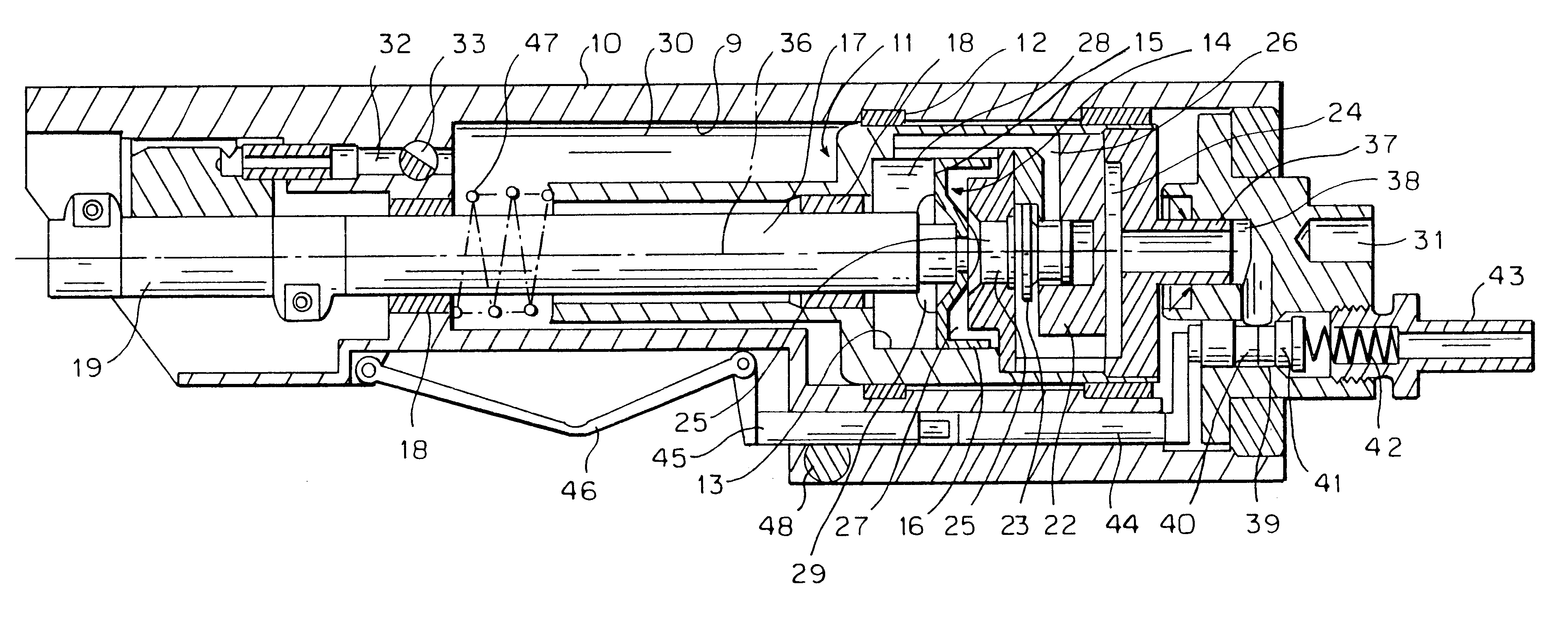
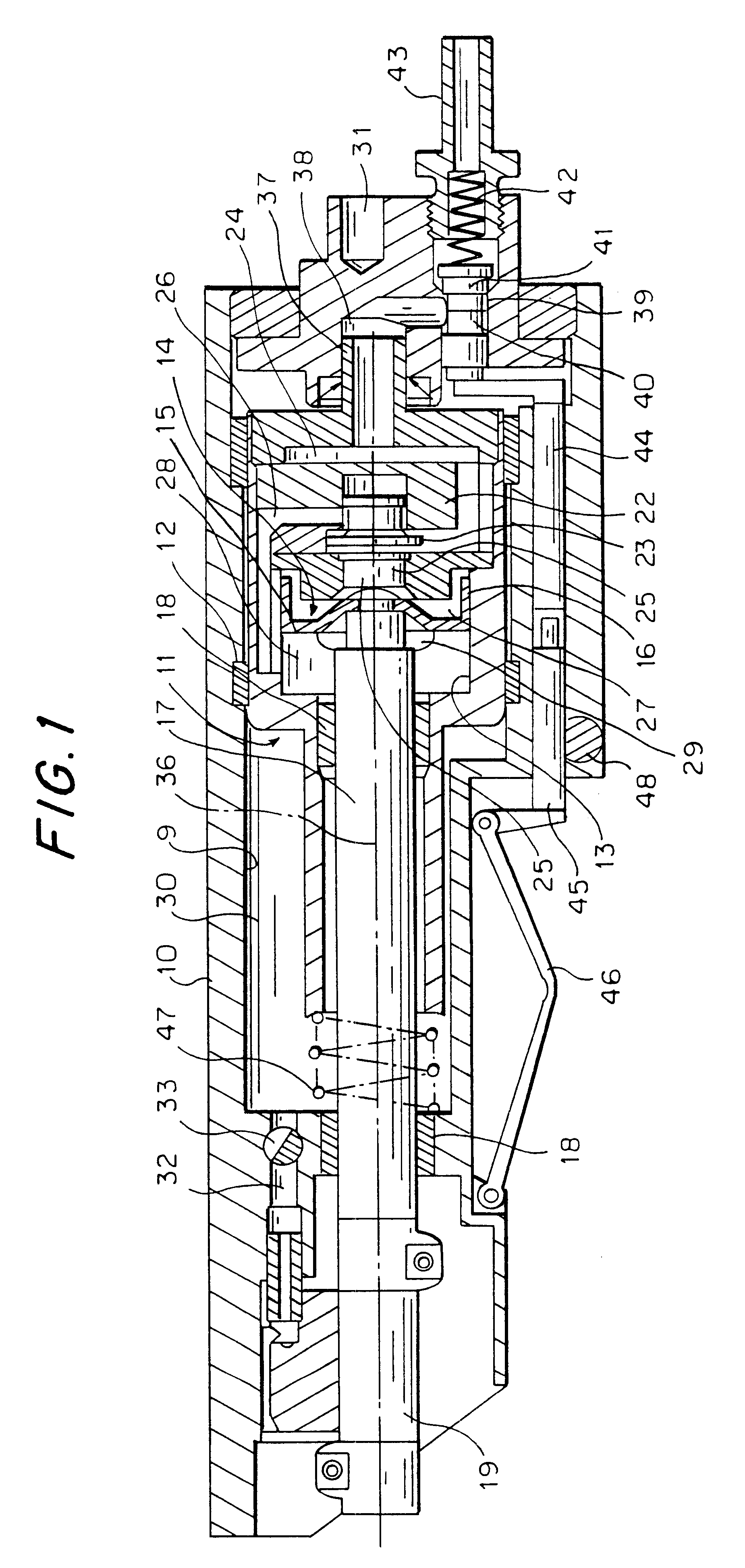
A motor casing 11 is mounted displaceably, on PTFE rings 12, in a cylindrical boring 9 in a handle 10. The casing 11 has a coaxial boring 13, in which a piston 14 is reciprocatingly mounted. The piston base 15 is thin-walled and convex and, at its periphery, merges into a thin-walled cylindrical sleeve 16. The piston 14 is connected to a coaxial piston rod 17 made from an aluminium alloy which is anodized. PTFE is incorporated in the anodized layer. This design of piston and piston rod provides them with a low mass. Consequently, the reaction forces which have to be damped are also reduced. The piston rod 17 is mounted displaceably in two sliding-contact bearings 18 in the handle 10 and in the casing 11. The rear sliding-contact bearing 18 at the same time serves as a seal for the front cylinder chamber 28. A tool holder 19 which may, for example, be designed and mounted as described in German Patent No. 29 39 896, is attached to the front end of the piston rod 17.

At the rear end of...


PUM

PropertyMeasurementUnit
pressureaaaaaaaaaa
forceaaaaaaaaaa
gravityaaaaaaaaaa

Abstract

A motor housing (11) is mounted in a handle body (10) so as to slide in the longitudinal direction. A tubular pipe (37) that can slide in a bore (38) of the body (10) projects from the back of the housing (11). Compressed air can be applied to the bore (38) through a switching valve (40). A piston (14) with a piston rod (17) can slide in the housing and a tool can be secured to its front end. A flutter valve (23) which alternatingly connects the bore (38) to the two cylinder chambers (27, 28) is built into the valve housing (22). The piston (14) alternatingly opens the connection to an outgoing air conduit (29-31). A pre-stressed spring (47) is set between the body (10) and the housing (11). In operation, the housing (11) oscillates out of step with the piston (14), so that their initial forces are largely compensated and no vibrations are transmitted to the handle body (10).

Description

1. Technical Field of the InventionHandtools with a pneumatic linear vibrating drive are known. They are used to saw, grind, polish, file and cut workpieces. The vibrating drive comprises a piston which is mounted displaceably in the handle and has a piston rod, to the front of which a tool holder is attached. The piston is driven by a flutter valve which alternately connects a cylinder chamber to the feed pressure which is supplied via a manually actuated pilot valve and to an exhaust air duct.2. Prior ArtEP-A-89 311 has disclosed a vibration damper for such a handtool. A damper mass is mounted in such a manner that it can be displaced in the longitudinal direction in the casing and is supported with respect to the casing by means of rubber springs. However, this vibration damper increases the length of the structure and is frequency-dependent.Moreover, DE-A-32 12 701 has disclosed a pneumatic hammer as described in the preamble of Claim 1. The hammer has a tool casing with a linea...

Claims


Application Information

Patent Timeline
Patent Type & Authority Patents(United States)
IPC IPC(8): B23D51/00B23D51/18B25F5/00
CPCB23D51/18B25F5/006
Inventor BOLLINGER, HEINRICHKELLER, MAX
Owner BIAX MASCHEN
Why Eureka
Try Eureka