Portable remote patient telemonitoring system

a remote patient and telemonitoring technology, applied in the field of monitoring vital signs and capturing data, can solve the problems of prolonging the duration of the trial, increasing the overall cost of the trial, and putting a lot of effort into human trials

Inactive Publication Date: 2002-07-09
CLEARPATH PARTNERS
View PDF130 Cites 1756 Cited by
  • Summary
  • Abstract
  • Description
  • Claims
  • Application Information

AI Technical Summary

Problems solved by technology

Successful human trials are critical to regulatory approval of a new drug or therapy, and accordingly, much money an effort goes into the human trials.
While a great deal of information can be gathered at such tests, generally there is no method for collecting the data between physician visits, thereby causing decisions regarding efficacy and safety to be made based on a small sampling of the patients' experiences with the drug and / or therapy.
More frequent visits to the physician would improve the data pool; unfortunately, such visits are expensive, add to the overall cost of the trial, and, because a limited data set is available, the trial duration is lengthened, thereby delaying the drug's market introduction.
Prior art patient telemetry systems have had limited commercial success for a variety of reasons such as difficult of use and cost.
Generally, wireless systems are problematic in the hospital setting because of the proximity of the respective patients and the amount of interference found in such a setting.
Remote monitoring of patients from their homes introduces an entirely new set of challenges for transmitting the gathered data to a central location for evaluation.
Numerous attempts have been made to facilitate such data collection and trasmission; however, in each case, cumbersome and uncomfortable monitoring equipment is placed on the patient and the patient is tethered to the monitoring equipment by electrical cords, thereby limiting the patient's movement.
In some prior art systems, the electrical cords have been removed and the transmissions to the monitoring equipment made using telemetry techniques; however, such systems have been used primarily for real-time vital signs monitoring and not for data collection of the type needed for diagnosis and efficacy and safety testing.
Moreover, such systems also limited the movement of the patient to a limited area near the vital signs monitor.
Each of the above-described telemetry systems is designed primarily for hospital use and include relatively expensive sensor arrays and processing devices for real-time patient monitoring and diagnosis.
Unfortunately, the sensor harness is quite cumbersome and conspicuous and includes sensors for performing an alert function rather than data collection and analysis functions.
While the precordial strip patch used by Segalowitz purportedly transmits vital signs data up to 50 meters, it requires a dual-stage operational amplifier chip, an encoder modulator chip, a wireless transmitter chip including an oscillator, and other costly components such as artificial intelligence software, sound and visual alarms, and a microprocessor.
As a result, the precordial strip patch is relatively expensive to manufacture and operate.
Otherwise, data is lost once the memory in the portable unit is full.
No mechanism is provided for continuously collecting data, at all times, in a way which requires no patient action.

Method used


Image

  • Portable remote patient telemonitoring system
  • Portable remote patient telemonitoring system
  • Portable remote patient telemonitoring system

Examples


case 1

This case defines the ARQ behavior when a single erroneous packet is detected and no further errors occur on the communications link 75 thereafter. FIG. 10C defines the mechanism. As illustrated in FIG. 10C, the signal transfer unit 20 sends a data packet which is incorrectly received at the base station unit 30, the base station unit 30 sends a NAK package which contains a data field pointing to the first detected erroneous packet, and the signal transfer unit 20 retransmits the data packet. As illustrated in FIG. 10D, an identical procedure is adopted if the signal transfer unit 20 fails to receive a packet from the base station unit 30.

case 2

This case defines the ARQ behavior when two erroneous packets are detected consecutively and no further errors occur on the communications link 75 thereafter. FIG. 10E defines the mechanism. As illustrated in FIG. 10E, the signal transfer unit 20 sends a data packet which is incorrectly received at the base station unit 30, and the base station unit 30 sends a NAK packet which is incorrectly received by the signal transfer unit 20. The signal transfer unit 20 then transmits a NAK which is correctly received at the base station unit 30 which then retransmits the first NAK packet containing a data field pointing to the first detected erroneous packet which is subsequently retransmitted by the signal transfer unit 20. As illustrated in FIG. 10F, an identical procedure is adopted if the signal transfer unit 20 fails to receive a packet from the base station unit 30.

case 3

This case defines the ARQ behavior when three erroneous packets are detected consecutively. FIG. 10G shows the mechanism. As illustrated in FIG. 10G, the base station unit 30 receives two consecutive erroneous packets and hence recognizes that the radio link has failed. No further reply is sent to the signal transfer unit 20 which, by implication, will inform the signal transfer unit 20 that the link has failed. The base station unit 30 then returns to receive mode and awaits re-establishment of the communications link 75 by a dialog request from the signal transfer unit 20. Similarly, if the first erroneous packet is received by the signal transfer unit 20, an identical mechanism is adopted as shown in FIG. 10H. This case also defines the situation where a correctly received packet lies between two erroneous packets as the receiving unit detects two consecutive erroneous data packets and considers the radio link to have failed. FIG. 10 illustrates the dialog in this case.

Packet For...


PUM


Abstract

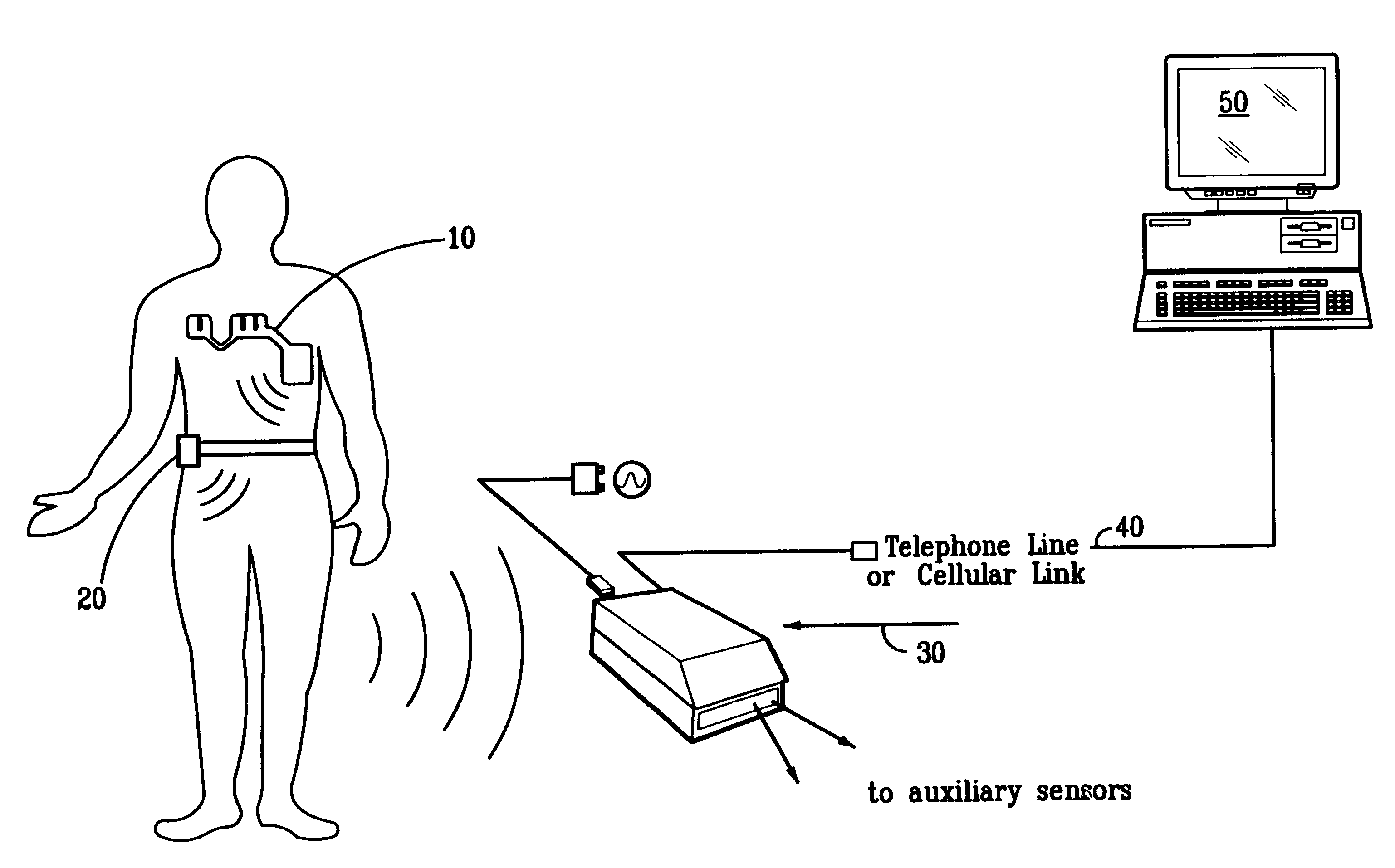
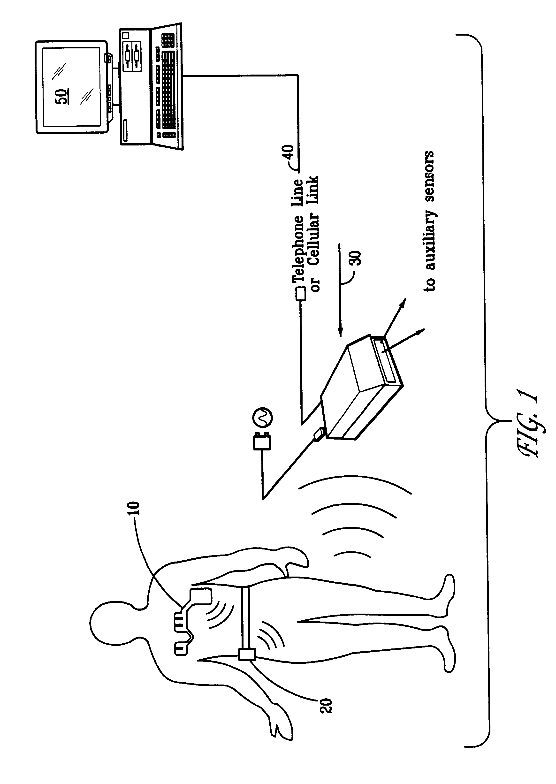
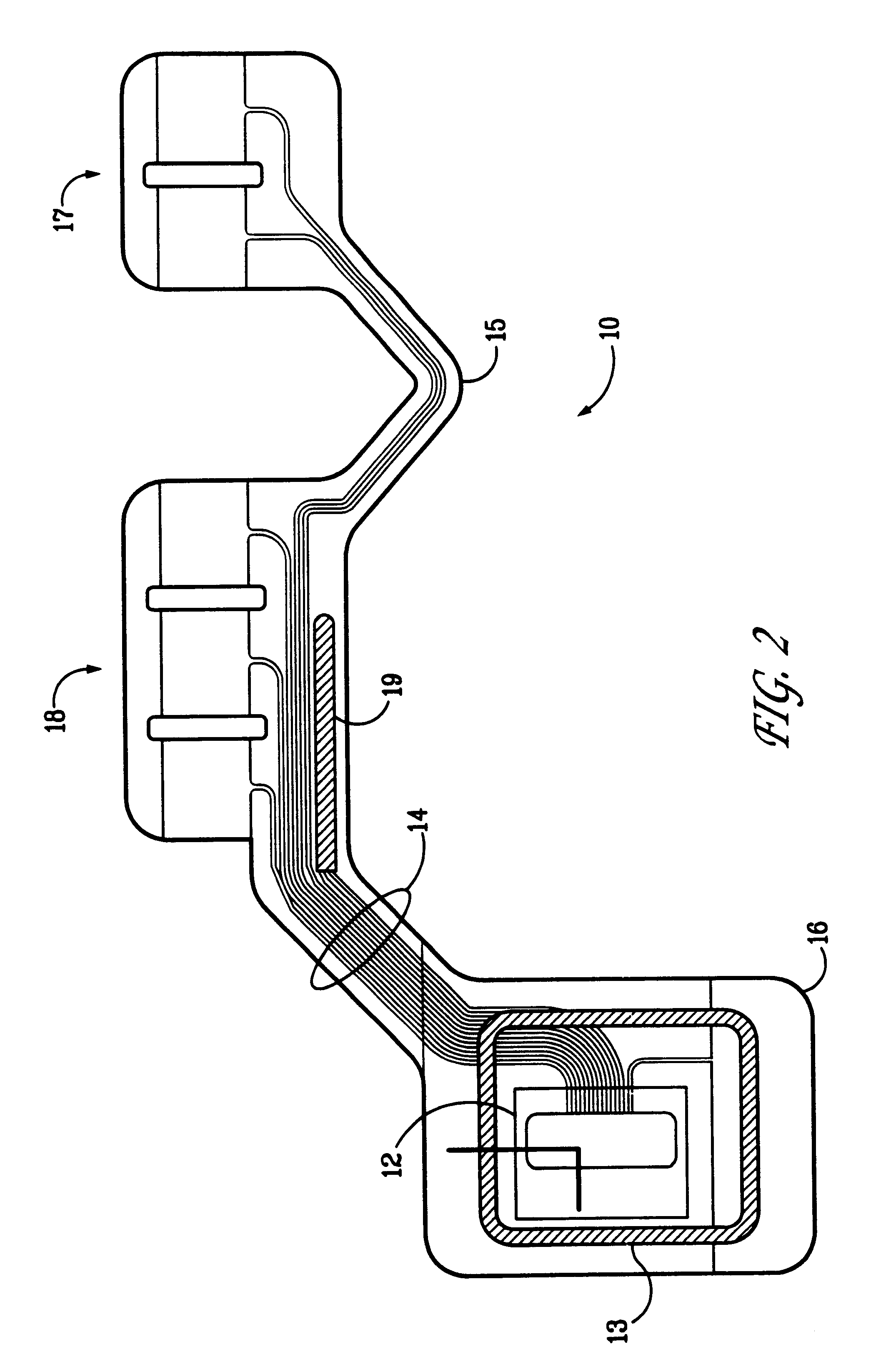
A system and method for monitoring vital signs and capturing data from a patient remotely using radiotelemetry techniques. The system is characterized by a cordless, disposable sensor band with sensors form measuring full waveform ECG, full waveform respiration, skin temperature, and motion, and transmission circuitry for the detection and transmission of vital signs data of the patient. A small signal transfer unit that can either be worn by the patient, e.g., on his or her belt, or positioned nearby receives data from the sensor band, which it then forwards by e.g., radio transmission to a base station that can be located up to 60 meters away. The base station receives data transmissions from the signal transfer unit and is designed to connect to conventional phone lines for transferring the collected data to a remote monitoring station. The base station may also capture additional clinical data, such as blood pressure data, and to perform data checks. Patient safety is enhanced by the ability of the base station to compare clinical data, e.g., ECG, against given profiles and to mark events when appropriate or when the base station is programmed to do so. Such events are indicated to the physician and could be indicated to the patient by reverse transmission to the signal transfer unit. A remote monitoring station allows the presentation and review of data (including events) forwarded by the sensor band. ECG analysis software and a user-friendly graphical user interface are provided to remotely analyze the transmitted data and to permit system maintenance and upkeep. The system of the invention has useful application to the collection of patient clinical data during drug trials and medical testing for regulatory approvals as well as management of patients with chronic diseases.

Description

1. Field of the InventionThe present invention relates to a system and method for monitoring vital signs and capturing data from a patient remotely using radiotelemetry techniques. In particular, the present invention is a low cost, patient-friendly, ambulatory monitoring system for remote electronic capture of nonincasive vital signs data including, e.g., full waveform ECG, repiration rate, skin temperature, and blood pressure. The present invention also has the capability for real-time monitoring or recording of continuous or point-in-time information with the data presented to the user in a tailored form. Monitoring software included in the system of the invention may also incorporate full ECG analysis as well as alarms for arrhythmias and other abnormalities determined from the measured vital signs.2. Description of the Prior ArtBefore drugs and related therapies are approved for widespread use by physicians, such drugs and therapies typically undergo numerous trials for efficac...

Claims


Application Information

Patent Timeline
Patent Type & Authority Patents(United States)
IPC IPC(8): A61B5/00G08C17/00A61B5/022A61B5/04A61B5/08A61B5/145G16H40/67H04Q9/00
CPCG06F19/323G06F19/3418A61B5/0006A61B5/0022A61B2560/0209Y10S128/903Y10S128/904A61B5/7232G16H10/65G16H40/67Y02A90/10
Inventor KUMAR, HARPAL S.JOHNSON, PAULLLEWELLYN, MICHAEL D.MULLARKEY, WILLIAM J.NEW, JR., WILLIAMNICOLSON, LAURENCE J.O'BRIEN, WILLIAM G.PLACE, JOHN D.RELPH, PETER M.
Owner CLEARPATH PARTNERS
Why Eureka
Try Eureka