Conductive antireflective coatings and methods of producing same

a technology of anti-reflective coatings and coatings, applied in the direction of natural mineral layered products, lighting and heating apparatuses, instruments, etc., can solve the problems of inability to improve beyond certain limits, limitations on carrier concentration and mobility, and inconvenient physical thickness specification of various layers

Inactive Publication Date: 2002-08-20
VITRO FLAT GLASS LLC
View PDF80 Cites 108 Cited by
  • Summary
  • Abstract
  • Description
  • Claims
  • Application Information

AI Technical Summary

Problems solved by technology

However, specifying the various layers by their physical thickness is not particularly useful because such measurements do not account for varying indices of refraction.
The various embodiments mentioned above provide adequate antireflectance and EMR shielding, but there are limitations in the above-described embodiments that may restrict optimizing the coating to certain electrical resistivity requirements while maintaining excellent broad band anti-reflection performance.
In practice, there are limitations on the carrier concentration and mobility that can be obtained, which cannot be improved beyond certain limits.
The tight thickness tolerances on these materials and the need for complex designs for anti-reflection properties makes the coatings difficult to manufacture and expensive.
This translates into additional costs in manufacturing the more complex designs.

Method used


Image

  • Conductive antireflective coatings and methods of producing same
  • Conductive antireflective coatings and methods of producing same
  • Conductive antireflective coatings and methods of producing same

Examples


example 2

Comparative Example

This example demonstrates the two-layer anti-reflection coating. The refractive index of the TCO layer is about 2.1 in the visible portion of light. The human eye is most sensitive to 550 nm light so a quarter wave of TCO would have a physical thickness of 655 .ANG. at this wavelength. The refractive index of the top layer of the 1 / 4-1 / 4 wavelength design is calculated from the following formula: refractive index of layer 2 is equal to the square root of the refractive index of layer 1 squared times the index of refraction of the incident medium divided by the index of refraction of the substrate. The refractive index of layer two is 1.71 for layer 1, the refractive index is 2.1, the refractive index for glass is 1.51 and the refractive index of incident medium 1.0. The physical thickness of layer 2 is 804 .ANG. for a 1 / 4 wave optical thickness at 550 nm. FIG. 11 is a graph generated using a commercial computer program to calculate the reflectance versus wavelengt...

example 3

The improvements over 1 / 4-1 / 4 wavelength design by the 1 / 3-1 / 5 wavelength design of the instant invention are demonstrated in this example. The optical constants of a fluorine-doped tin oxide were determined as a function of wavelength in the visible spectrum using a variable angle spectroscopic ellipsometer and are listed in Table 3.

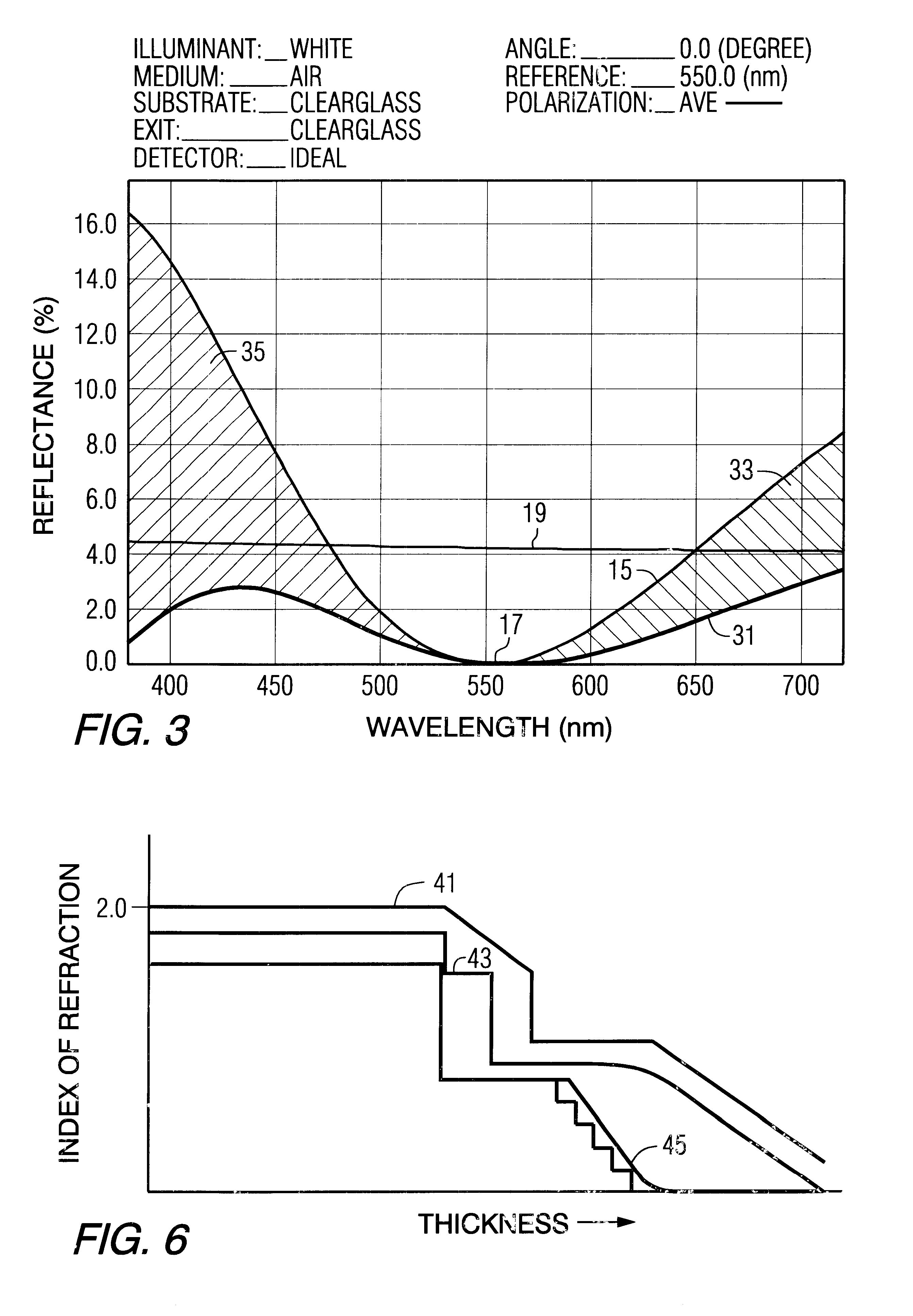
The physical thickness of the fluorine-doped tin oxide layer is 1060 .ANG. for an approximate 1 / 3 optical thickness at a design wavelength of 550 nm using the above-discussed relationship for optical thickness. The second layer is a silica layer with a refractive index of 1.45 and a physical thickness of 778 .ANG. for a 1 / 5 optical thickness at a design wavelength of 550 nm. The reflectance as a function of wavelength is calculated using a commercial thin film software package and is shown in FIG. 5 curve 31. The photopic reflectance is 0.44% and the average reflectance is 1.5%. Comparing this to the 1 / 4-1 / 4 wavelength design described in Example 2, the...

example 4

The 1 / 3-1 / 5 anti-reflection design of the instant invention has utility in applications where TCOs and their index restrictions do not occur. Table 4 is a list of anti-reflection designs that partially demonstrate the scope of the instant invention. The reflectance values listed in Table 4 were calculated using a commercial thin film program. Column 1 lists the thickness of layer 2, column 2 lists the refractive index of layer 2, column 3 lists the thickness of layer 1, column 4 lists the refractive index of layer 1, column 5 lists the optical thickness of layer 2, column 6 lists the optical thickness of layer 1 and column 7 lists the photopic reflectance for the designs. Row 15 is a 1 / 4-1 / 4 wavelength design showing the high photopic reflectance.


PUM

PropertyMeasurementUnit
sheet resistanceaaaaaaaaaa
refractive indexaaaaaaaaaa
reflectanceaaaaaaaaaa

Abstract

This invention relates to a two layers or more anti-static film coating deposited on a substrate. Selected layers of the films may have anti-static and/or electromagnetic properties. In one embodiment, the film farthest from the substrate has an index of refraction lower than the underlying film. In another embodiment, the surface of the film is roughened to provide a graded index of refraction.

Description

1. Field of the InventionThis invention relates to multilayered antireflective coatings, articles having such coatings, and methods for making same.2. Description of the TechnologyIt is known that a surface will reflect light and that the amount of light reflected from the surface will increase as the viewing angle increases. The reflected light from the surface of a substrate may be objectionable when an observer is viewing a transmitted image through the substrate, e.g., a cathode ray-tube (hereafter "CRT"), architectural glazing, a glass covering a picture, or the lens of an optical instrument or eyeglasses. The reflected light is objectionable because it obscures the transmitted image, and the transmitted image may become indiscernible if the reflected light is too intense. Viewing an image that is obscured by reflected light may cause eye strain for the observer. Further, the reflectance light may be objectionable for aesthetic reasons, as for example in the case of architectur...

Claims


Application Information

Patent Timeline
Patent Type & Authority Patents(United States)
IPC IPC(8): B32B3/26B32B7/02G02B1/11
CPCG02B1/116Y10T428/265Y10T428/24975Y10T428/24942G02B1/16
Inventor SOPKO, JOHN F.OKOROAFOR, MICHAEL O.LI, HUAWENNEUMAN, GEORGE A.
Owner VITRO FLAT GLASS LLC
Why Eureka
Try Eureka