
Magnetic resonance imaging apparatus

a magnetic resonance imaging and apparatus technology, applied in the field of magnetic resonance imaging apparatus, can solve the problems of blackened flow images or artifacts, the pc method produces a problematic aliasing artifact, and the inability to distinguish between arterial flow and vein flow, so as to improve the ability to image blood flow, the effect of suppressing the signal intensity of the static par

Inactive Publication Date: 2002-08-27
HITACHI MEDICAL CORP
View PDF5 Cites 33 Cited by
  • Summary
  • Abstract
  • Description
  • Claims
  • Application Information

AI Technical Summary

Benefits of technology

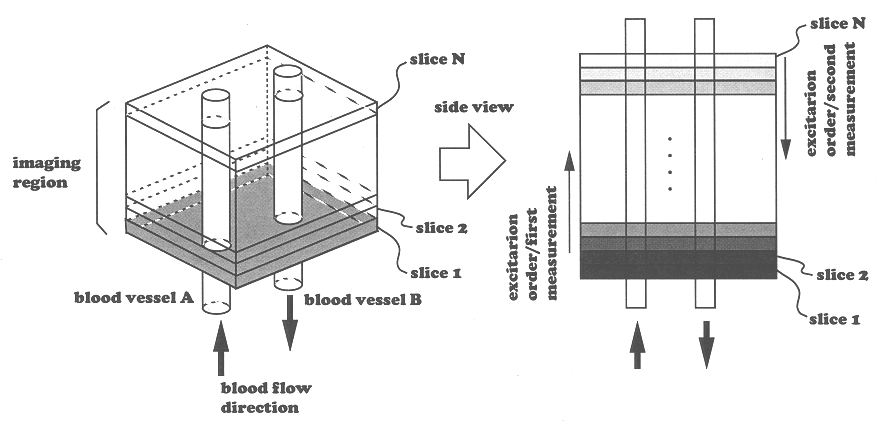
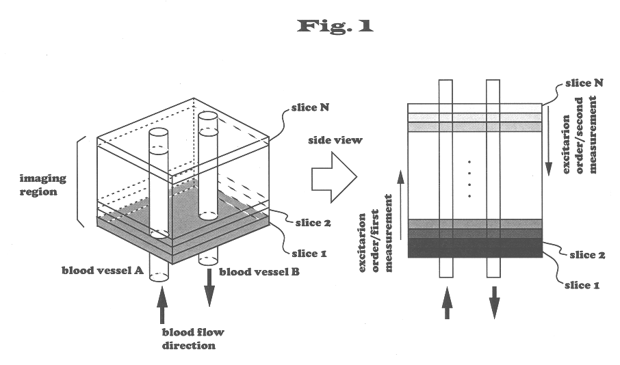
In the slice positioned at each side of the object region, signals of blood spins flowing into the slice would not be suppressed by multiple excitations and would not be distinguished from those from blood spins flowing out of the slice. However, by pre-saturating the region adjacent to the object region, signals are suppressed by multiple excitations and, therefore, blood spins of different directions, i.e., inflow spins and outflow spins, become distinctive. Thus, ability of imaging blood flow can be improved throughout the object region. Instead of pre-saturating the region adjacent to the object region, data of slices at both sides may be deleted from data to be processed in step (b). This deletion of data should be construed as being within the scope of the present invention.
When each slice is excited so that the adjacent slices overlap each other, a static part of the overlapped portion is repeatedly excited and, therefore, signal intensity of the static part can be more suppressed than when slices do not overlap. Thereby, the blood flow imaging ability can be improved.

Problems solved by technology

In addition, since signals of flow spins flowing into the region from any direction are enhanced, arterial flow and venous flow cannot be distinguished.
However, when the flow velocity is high enough to cause a phase shift of more than .pi., the PC method produces a problematic aliasing artifact.
In addition, since the sequence of the PC method is not of the flow-rephase type, it cannot cope with turbulent flow or variance of the flow velocity, and blackened flow images or artifacts are therefore likely to occur.
Moreover, a two-dimension PC method aiming at quantitative measurement of flow velocity cannot thicken the thickness of a slice including blood vessels and is not suitable for observing the overall travel of blood together with quantitative measurement.

Method used


Image

  • Magnetic resonance imaging apparatus
  • Magnetic resonance imaging apparatus
  • Magnetic resonance imaging apparatus

Examples


Embodiment Construction

The present invention will now be explained in detail with reference to the specific examples shown in the appended drawings.

FIG. 8 is an overall block diagram showing the system of an MRI apparatus that can be used according to the present invention. This MRI apparatus is for obtaining tomograms of an object to be examined by utilizing NMR phenomenon, and comprises a static magnetic field generating magnet 2, a gradient magnetic field generating system 3, a transmitting system 5, a receiving system 6, a signal processing system 7, a sequencer 4 and a central processing unit (CPU) 8, as shown in FIG. 8.

The static magnetic field generating magnet 2 generates a uniform static magnetic field around an object to be examined 1 in a direction parallel or perpendicular to the body axis of the object 1 and comprises a magnet for generating static magnetic field in a space around the object 1 such as a permanent magnet, a resistive magnet or a superconductive magnet.

The gradient magnetic fie...


PUM


Abstract

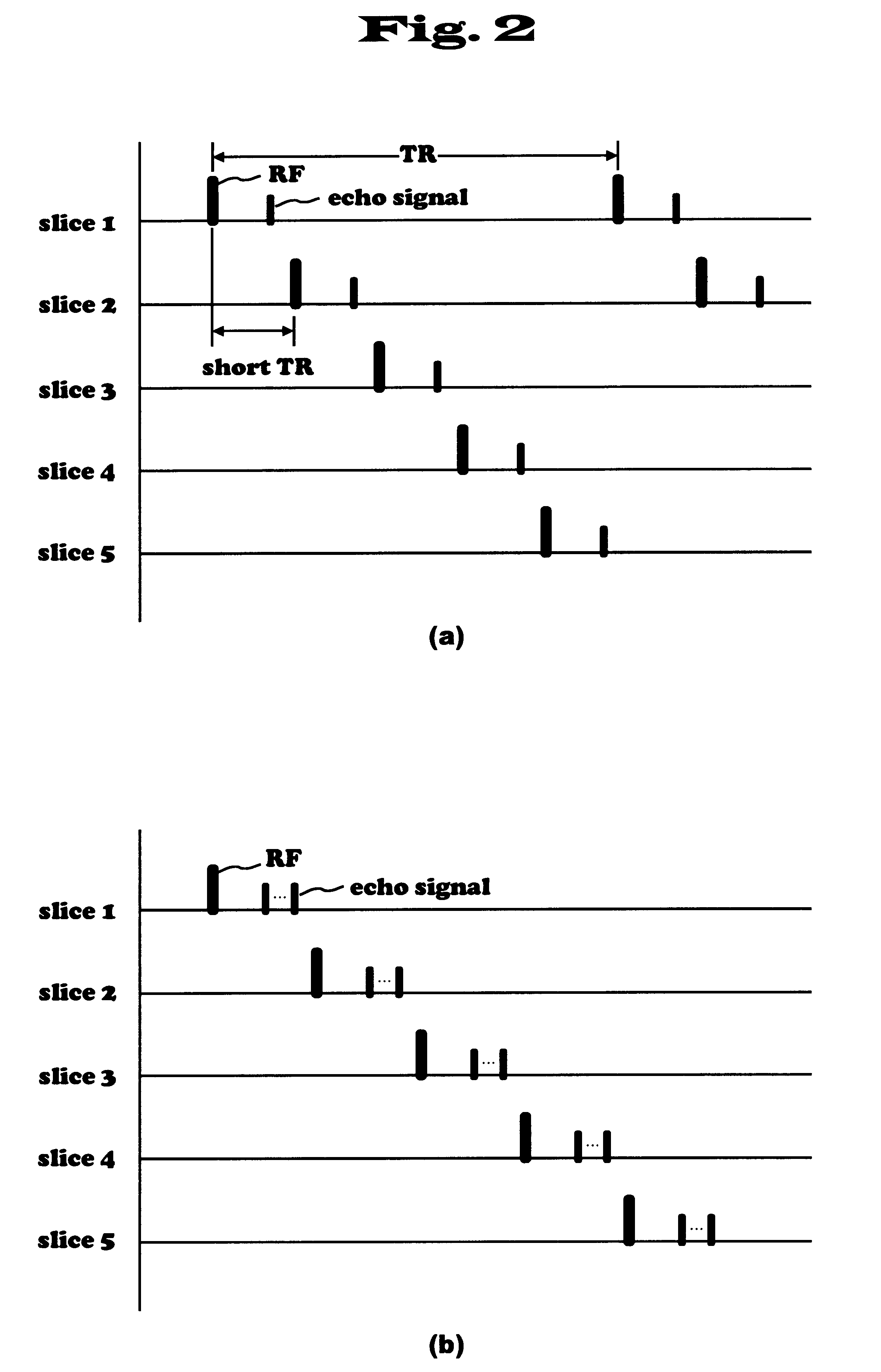
An MRI apparatus having an ability of displaying images of flow in different directions in distinguishable manner. When this MRI apparatus performs multi-slice acquisition with a predetermined repetition time TR by selecting a plurality of slices approximately perpendicular to the flow direction of an object to be examined, it performs a first measurement of exciting the plurality of slices in a first order and a second measurement of exciting the same slices in the opposite order to obtain two kinds of data whose signal intensity differs depending on the flow direction. The two kinds of data obtained by two measurements are subjected to subtraction operation to obtain data with different signs depending on the flow direction. These signs combined with the signal intensity are made into images where flow in opposite directions are distinctively depicted. In the multi-slice acquisition, slices are selected so that adjacent slices partially overlap in the direction of the thickness of the slice. Thereby signals of a static part can be suppressed and contrast of flow images after substraction can be enhanced. EPI method of very short imaging time can be employed for the imaging sequence of MRA according to the present invention.

Description

The present invention relates to a magnetic resonance imaging (abbreviated as "MRI" hereinafter) apparatus for obtaining tomograms of desired sections of an object to be examined by utilizing nuclear magnetic resonance (abbreviated as "NMR" hereinafter). In particular, it relates to an MRI apparatus capable of distinguishing the direction of blood flow when depicting the travel of blood flow.RELATED ARTOne known imaging ability of an MRI apparatus is MR angiography (abbreviated as "MRA" hereinafter), which depicts blood flow without using an imaging contrast agent or the like. Typical imaging methods of blood flow using the MRI apparatus include the time-of-flight (TOF) method, which utilizes the inflow effect of blood into slice planes, and the phase method, which utilizes phase dispersion of flow spins caused by gradient magnetic field in the direction of the flow. The phase method includes the phase-sensitive (PS) method and the phase-contrast (PC) method. The PS method depicts b...

Claims


Application Information

Patent Timeline
IPC IPC(8): A61B5/055G01R33/54G01R33/563A61B5/026
CPCA61B5/055G01R33/563A61B5/026G01R33/4835
Inventor WATANABE, SHIGERU
Owner HITACHI MEDICAL CORP
Learn More