Gravity flow sludge load-out system

Inactive Publication Date: 2002-09-10
RDP TECH
View PDF6 Cites 44 Cited by
  • Summary
  • Abstract
  • Description
  • Claims
  • Application Information

AI Technical Summary

Problems solved by technology

The treatment and disposal of large volumes of sewage sludge has been a problem for many years.
However, providing this degree of accuracy while simultaneously providing high throughput has not been achieved by prior art known to the present time.
The source of the problem lies in large fluctuations in sludge flow rates, due, in turn, to large fluctuations in sludge viscosity caused by batch variants in sludge dehydration and temperature, and varying material heights or head pressures in the loading hoppers.
Another challenge in designing a slud

Method used


Image

  • Gravity flow sludge load-out system
  • Gravity flow sludge load-out system
  • Gravity flow sludge load-out system

Examples


Embodiment Construction

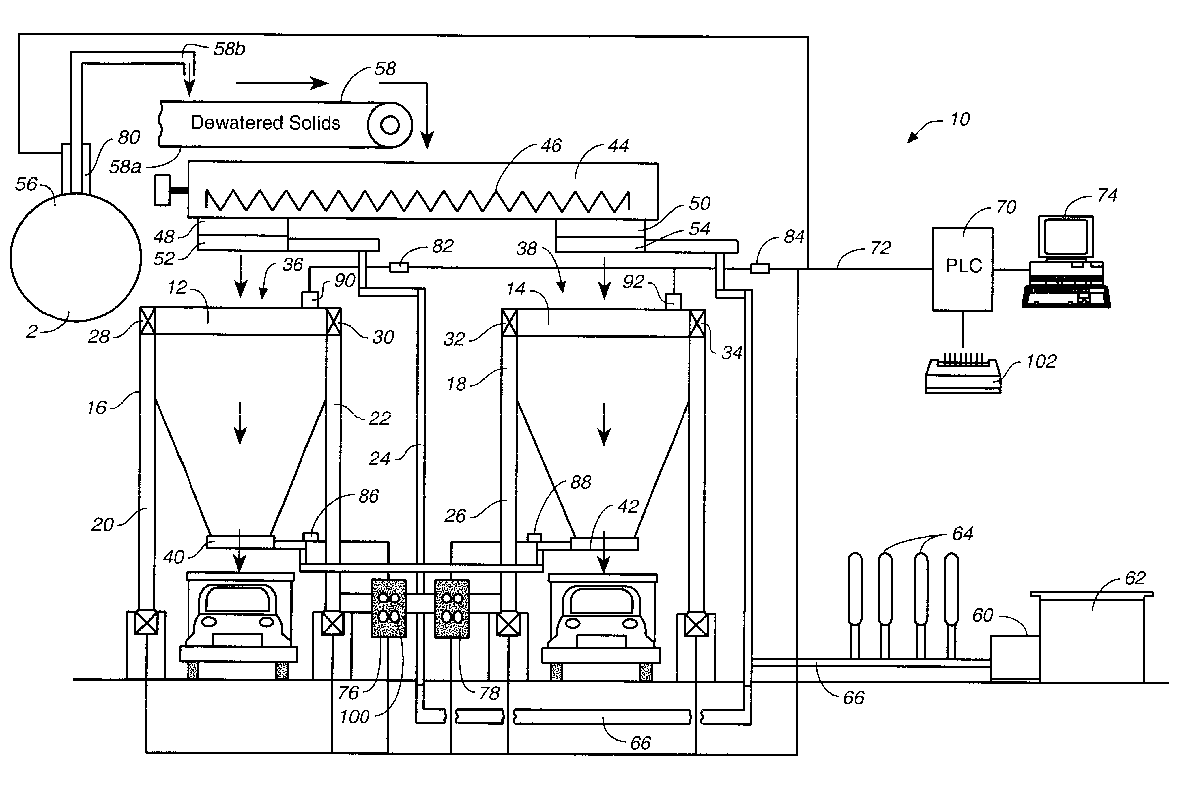
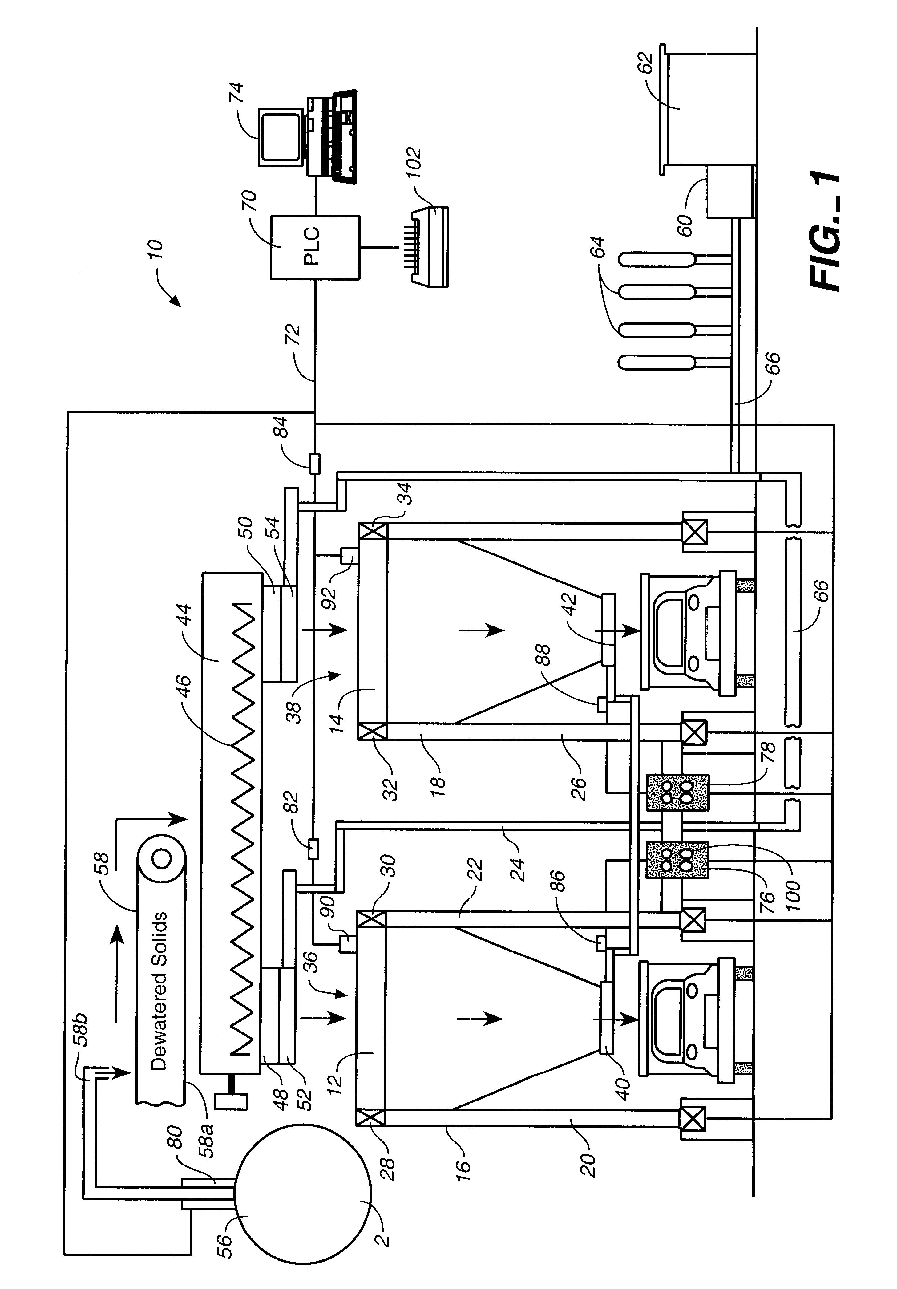
FIG. 1 is a front elevation schematic view of the gravity flow sludge-load out system 10 of the present invention. This view shows that the system comprises at least one hopper. The system shown is a dual station system including a first hopper 12, and a second hopper 14, each with a large storage capacity, preferably at least 150 cubic yards, and each supported by a main structure 16 and 18. The support structures comprise a plurality of vertical support members 20, 22, 24, and 26. Each hopper rests on a dedicated load cell, 28, 30, 32, and 34. Alternatively, the support members may be support on load cells, though it is preferable for the hoppers alone to rest on the cells.

Each hopper has at least one inlet at the top, 36 and 38, respectively, for the introduction of sludge from the dewatering facility. Each hopper further includes a hydraulically controlled metering gate at the bottom, 40 and 42, respectively. A metering gate suitable for use in the system shown in FIG. 1, both a...


PUM

PropertyMeasurementUnit
Flow rateaaaaaaaaaa
Volumeaaaaaaaaaa
Gravityaaaaaaaaaa

Abstract

A gravity flow sludge load-out system for rapid and accurate loading-out of large volumes of treated biosolids from a wastewater dewatering plant, said system includes a plurality of hoppers 12, 14 supported by a main structure 16 having a plurality of vertical support members 20, each resting on a load cell 28, a sludge inlet at the tip of each hopper, and hydraulically controlled metering gates 40 at the bottom. A PLC 70 controls delivery of sludge from a dewatering facility, including e.g. a dewatering centrifuge 56, into the hoppers and then controls load-out of the sludge to a container truck by providing real-time monitoring of net sludge load-out and tight control of metering gates.

Description

CROSS REFERENCE TO RELATED APPLICATIONSNot applicable.1. Field of the InventionThe present invention relates generally to systems for loading out large volumes of dewatered biosolids for transport, reuse, and disposal, and more particularly to a gravity flow sludge load-out system for rapid and highly controlled automated loading out of biosolids into container trucks.2 Discussion of Related ArtThe treatment and disposal of large volumes of sewage sludge has been a problem for many years. Numerous methods have been devised to render biological sludge generally pathogen free and suitable for reuse as soil amendment and fertilizer; and numerous other methods have been devised to make unusable sludge easier to transport for disposal. However, regardless of its ultimate destiny, treated sludge is typically stored briefly at a sewage treatment facility and then loaded out into containers for transport either to sludge customers or to disposal sites. And in facilities with high wastewater...

Claims


Application Information

Patent Timeline
IPC IPC(8): G01G13/02G01G13/00
CPCG01G13/024
Inventor SIMON, RICHARD D.WILSON, RICHARD H.
Owner RDP TECH
Why Eureka
Try Eureka