Axial swage fitting for large bore pipes and tubes

a technology of axial swage and pipe, which is applied in the field of fittings, can solve the problems of insufficient pipe retention capability of existing swaging tools, inability to meet the requirements of swaging techniques widely used in pipe and tube with large diameter, and insufficient swaging force to deform the sleeve and pipe during swaging, so as to improve couplings and improve couplings. the effect of coupling capacity and enhanced tensil

Inactive Publication Date: 2002-09-17
MECH1
View PDF25 Cites 68 Cited by
  • Summary
  • Abstract
  • Description
  • Claims
  • Application Information

AI Technical Summary

Benefits of technology

The present invention provides a fitting for joining pipes, tubes, or conduits (hereinafter collectively "pipes"). Preferably, the fitting improves couplings of a large bore pipe, generally of 2 inches and larger in diameter. The improved coupling capability is a result of an enhanced tensile strength capacity in the fitting that keeps forces, which may result from high burst pressures and the like, from pulling a pipe axially away from the fitting The fitting includes a substantially cylindrical sleeve, which has an inner surface defining a bore, configured to slidably receive the pipe at an open end. The inner surface of the sleeve includes protrusions, which grip the outer surface of the pipe upon swaging. The outer surface of the sleeve includes multiple stepped lands of ascending height relative to the open end. The fitting further includes a substantially cylindrical swaging ring. An inner surface of the swaging ring includes multiple contact surfaces of descending height configured to engage the multiple ascending steps on the sleeve with an interference fit. Axial motion of the swaging ring causes the swaging ring to slide over the sleeve and apply a radial swaging force directly to the multiple stepped sleeve. The swaging force makes the ring overcome the interference and inwardly push the multiple ascending steps of the sleeve, which swages the sleeve to the pipe. Advantageously, the multiple ascending steps of the sleeve are positioned relative to the descending steps of the ring, such that only one stepped portion at a time is swaged.

Problems solved by technology

Although, swage fittings are well known in the industry, swaging techniques are not widely used on pipes and tubes with large diameters, in high pressure applications.
One reason for this is that, existing swaged fitting designs generally lack the requisite pipe retention capability, necessary for large bore, high pressure applications.
Moreover, since most swaged fittings are not designed for large bore pipes, the swaging force necessary to deform the sleeve and pipe during swaging, is usually beyond the capability of existing swaging tools.
The high strength and force requirements of such applications, tend to drive the relative size of the fitting, the swaging time, and the costs associated with manufacture, to prohibitive levels.
Although, these types of connections are commonplace, they are generally plagued with a variety of drawbacks, which make them high cost, high risk, and / or time consuming alternatives to the present invention.
For example, welded pipe joints usually require additional pre- and post-weld preparation events that are usually expensive and time consuming, such as pipe end preparation, post weld, grinding, non destructive inspection and hydro-testing.
Welds in pipes have also been known to fail at weak spots in heat affected areas adjacent to the welds.
Moreover, welding in the vicinity of potentially flammable fluids such as fuel and oil which may be used in the pipes or tubes, is inherently risky.
Flanged and bolted connecting systems require that the pipe ends be flared prior to use which may be inconvenient, expensive, and time consuming.
In many instances vibrations or other general usage may loosen bolts and cause leaks.
Moreover, gaskets are prone to failure after time or are easily damaged, which may further result in leaks.
Threaded systems, require pipe ends to be threaded, which can be time consuming and ineffective.
However, after a period of time, the sealant can deteriorate, which leads to leaking.

Method used


Image

  • Axial swage fitting for large bore pipes and tubes
  • Axial swage fitting for large bore pipes and tubes
  • Axial swage fitting for large bore pipes and tubes

Examples


Embodiment Construction

Embodiments of the present invention will be described with reference to the aforementioned figures. These figures have been simplified for ease of understanding and describing the embodiments.

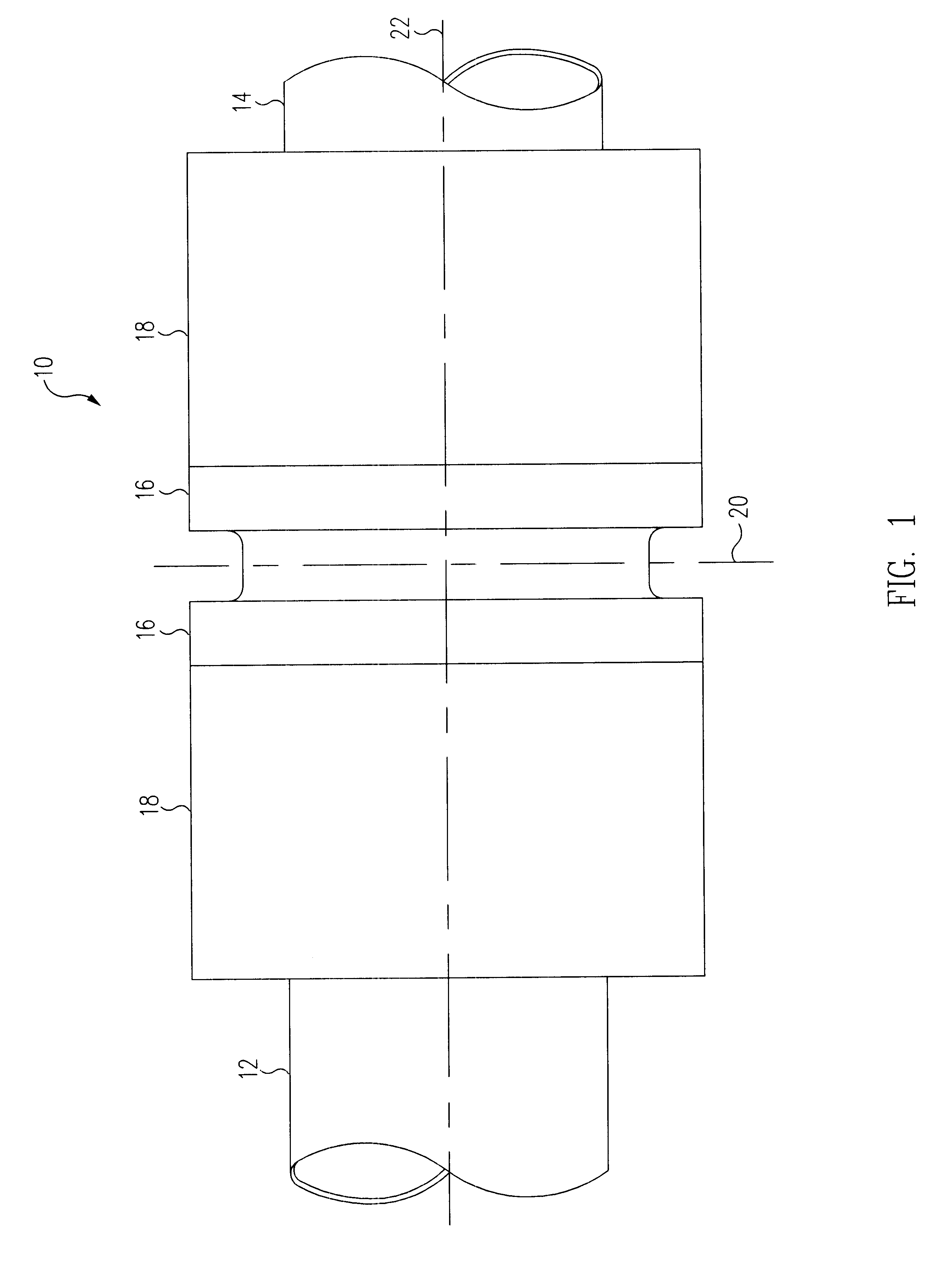
FIG. 1 is an external view of a fitting 10 in accordance with an embodiment of the present invention. Fitting 10, which includes a sleeve 16 and two swage rings 18, can be used equally well to secure together pipes, tubes, conduits, and the like. As shown in FIG. 1, fitting 10 is broadly symmetrical about centerline 20 and central axis 22. Thus, the description of fitting 10 will be directed to only one end of fitting 10, with reference to the other end, only when necessary to describe a feature of the invention, since it is understood that the other end is structurally and functionally the same. However, depending on the application for fitting 10, a complete fitting may include only one end of fitting 10, such as when the fitting is used to cap the end of a pipe. Moreover, fitting 10 is not ...


PUM

PropertyMeasurementUnit
diameteraaaaaaaaaa
burst pressuresaaaaaaaaaa

Abstract

A fitting for joining pipes, tubes, or conduits improves coupling capability particularly to a large bore pipe, generally of 2 inches and larger in diameter. The fitting includes a substantially cylindrical sleeve and ring. The sleeve has an inner surface defining a bore, configured to slidably receive the pipe at an open end. The inner sleeve surface also includes protrusions, which deform the outer surface of the pipe upon swaging. The fitting also includes an outer surface having multiple stepped lands of ascending height relative to the open end. The ring has an inner surface configured to engage the multiple ascending steps on the inner sleeve surface. The inner surface of the ring has descending steps that are positioned to interfere with the multiple ascending steps on the outside of the sleeve. Axial motion of the ring causes the ring to slide over the sleeve and apply a radial swaging force directly to the multiple stepped sleeve. The swaging force makes the ring overcome the interference and push down on the multiple ascending steps of the sleeve, which swages the sleeve to the pipe. The multiple ascending steps of the sleeve are positioned relative to the descending steps of the ring, such that only one step at a time is swaged.

Description

1. Field of the InventionThis invention relates to fittings and in particular to an axial swage fitting for pipes and tubes.2. Description of Related ArtFittings of various types are commonly used to couple tubes and pipes for a variety of applications. For example, in the aerospace industry, swage fittings are used to couple hydraulic lines, fuel lines, and the like, which convey fluids in aircraft and other vehicles. The coupling generally involves the deformation of a portion of the tube or pipe and the deformation of the fitting in response to the application of a swaging force to the fitting. The swage methodology is described in numerous patents, for example, U.S. Pat. No. 3,675,949 and U.S. Pat. No. 3,893,718.Various fittings have been developed which use the above referenced methodology to connect tubes. For example, U.S. Pat. No. 4,482,174 discloses an apparatus having a sleeve and a locking slidable over at least the first end of the sleeve, which has a reverse taper confi...

Claims


Application Information

Patent Timeline
Patent Type & Authority Patents(United States)
IPC IPC(8): B21D39/04F16L13/14
CPCB21D39/04F16L13/146F16L13/142Y10T29/49934
Inventor SURESH, SRINIVAS B.
Owner MECH1
Why Eureka
Try Eureka