Time domain measurement and control system for a hot wire air flow sensor

a technology of air flow sensor and time domain measurement, which is applied in the direction of volume/mass flow measurement, measurement devices, instruments, etc., can solve the problems of previously known analog control systems for hot wire air flow sensors, which have not been wholly satisfactory in operation, and previously known systems suffer from relatively slow response times and relatively high steady state errors

Inactive Publication Date: 2002-09-24
HITACHI AMERICA
View PDF14 Cites 23 Cited by
  • Summary
  • Abstract
  • Description
  • Claims
  • Application Information

AI Technical Summary

Benefits of technology

Any conventional means, such as a PID controller, can be utilized to vary either the pulse width or pulse frequency in order to maintain the amplitude of the pulse train at the output end of the heating element substantially constant.

Problems solved by technology

These previously known analog control systems for hot wire air flow sensors, however, have not proven wholly satisfactory in operation.
These previously known systems suffer from relatively slow response times and relatively high steady state error.
Furthermore, the required warming time for the air flow sensor in many cases is unsatisfactory.
A still further disadvantage of these previously known analog control hot wire air flow sensors is that the control system for such air flow sensors required operational amplifiers, a Darlington pair transistor and other resistors and capacitors to provide the correct feedback gains and offsets for the air flow sensor.
As such, these previously known control systems for hot wire air flow sensors were relatively expensive due to their multiplicity of components.

Method used


Image

  • Time domain measurement and control system for a hot wire air flow sensor
  • Time domain measurement and control system for a hot wire air flow sensor
  • Time domain measurement and control system for a hot wire air flow sensor

Examples


Embodiment Construction

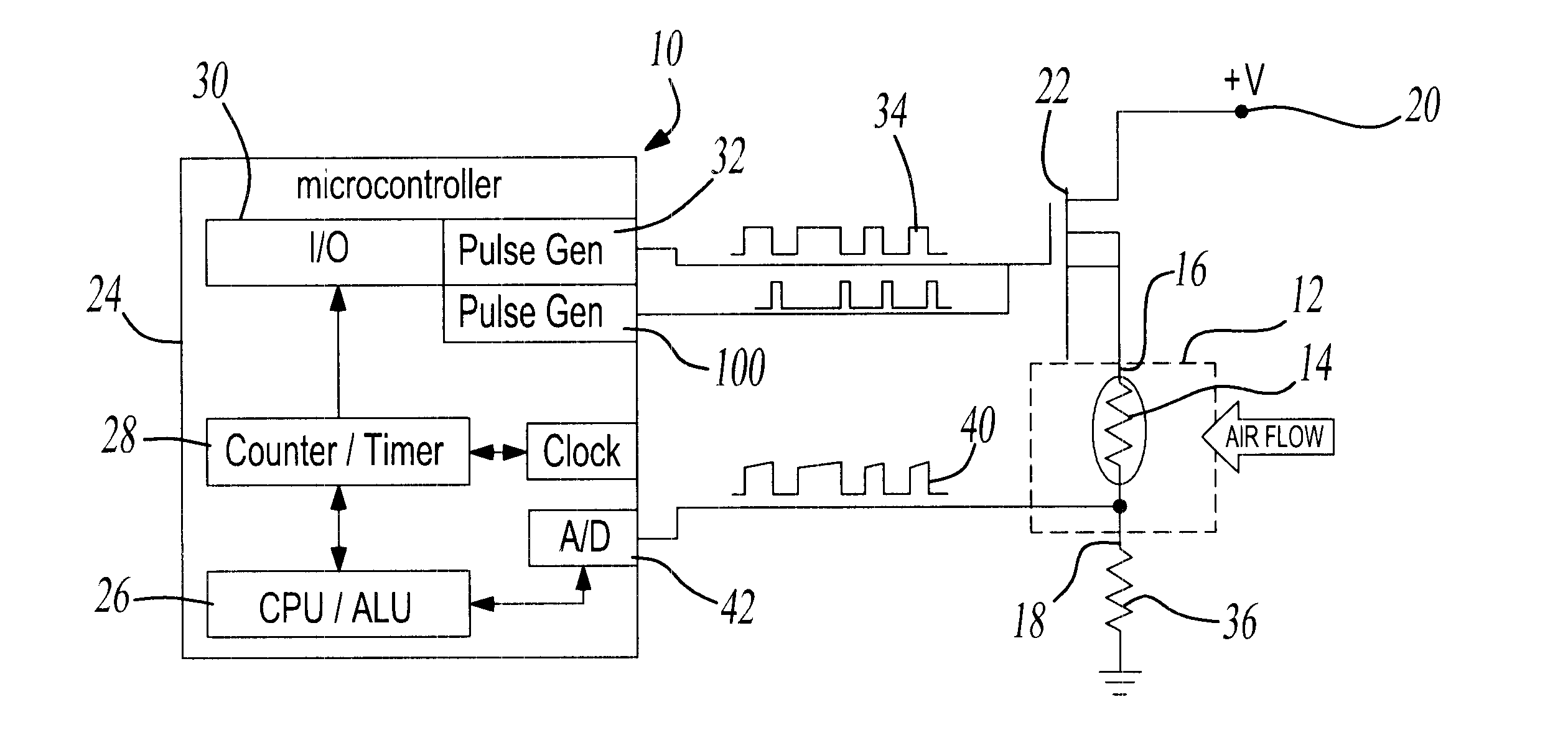
With reference first to FIG. 1, a block diagrammatic view of a first preferred embodiment of the time domain measurement and control system 10 for a hot wire air flow sensor 12 (illustrated only diagrammatically) is shown. In the conventional fashion, the air flow sensor 12 includes a resistive heating element 14 having an input end 16 and an output end 18. The input end 16 of the heating element 14 is connected to a voltage source 20 through an electronic switch 22, illustrated in FIG. 1 as a MOSFET, output end 18 is connected through a resistor 36 to ground. Thus, whenever the switch 22 is closed, current flows from the source 20 and through the resistive heating element 14 to ground.

In the conventional fashion, the temperature differential between the heating element 14 and ambient air is maintained at a predetermined constant, e.g. 200.degree. C. Furthermore, the power consumption of the heating element 14 is proportional to the air flow across the heating element 14 since such ...


PUM


Abstract

A time domain measurement and control system for a hot wire air flow sensor is disclosed in which the air flow sensor is of the type having a resistive heating element with an input end and an output end. The control system includes a fixed frequency variable width pulse generator which generates a pulse train through the heating element. This pulse train, furthermore, has a first predetermined voltage amplitude. The output voltage amplitude of the pulse train is determined at the outlet end of the heating element while a control circuit varies the duty cycle of the pulse train to maintain the output voltage amplitude at a second predetermined voltage level. The duty cycle of the pulse train is proportional to the air flow rate through the air flow sensor. In a modification of the invention, a fixed width variable frequency pulse train is generated through the resistive heating element and the frequency of the pulse train is varied to maintain the output voltage amplitude of the pulse train at the outlet end of the resistive heating element at a second predetermined voltage level. In this modification, the frequency of the pulse train is proportional to the air flow rate through the air flow sensor.

Description

I. Field of the InventionThe present invention relates to a time domain measurement and control system for a hot wire air flow sensor.II. Description of the Prior ArtMany automotive engine systems utilize hot wire air flow sensors in order to determine the air flow rate into the engine. This air flow rate, in conjunction with other engine parameters, is then utilized by a fuel management system which regulates and controls the operation of the engine.These previously known hot wire air flow sensors utilize a resistive element based upon a linear analog proportional feedback control signal. This control signal varies the current flow through the resistive element by an amount sufficient to maintain the temperature differential between the resistive element and ambient air at a predetermined constant, typically 200.degree. C. The magnitude of the current flow through the resistive element is then proportional to the air flow through the air flow sensor.These previously known analog co...

Claims


Application Information

Patent Timeline
Patent Type & Authority Patents(United States)
IPC IPC(8): G01F1/698G01F1/696F02D35/00
CPCG01F1/6986
Inventor SAIKALIS, GEORGEOHO, SHIGERUDIPIERRO, MARCO
Owner HITACHI AMERICA
Why Eureka
Try Eureka